Data transfer method and disk control unit using it

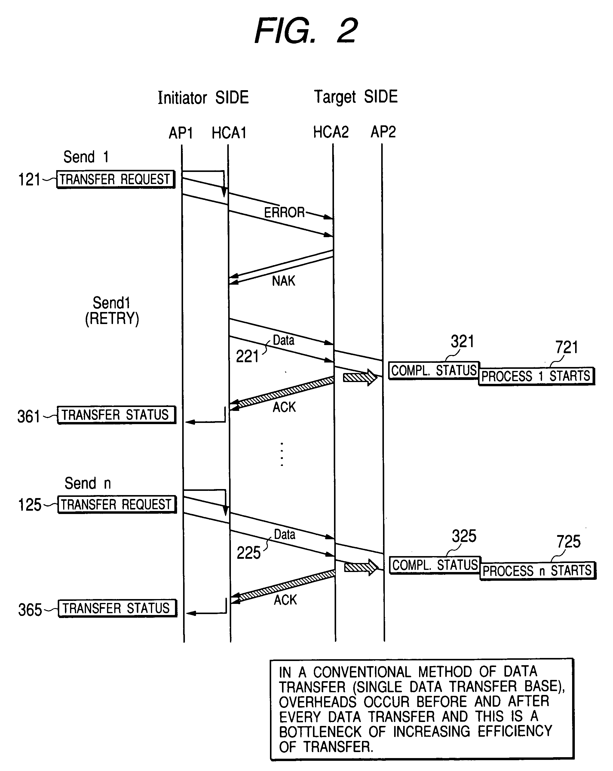
a data transfer and disk control technology, applied in the direction of instruments, input/output to record carriers, computing, etc., can solve the problems of significant decrease in communication channel efficiency, relatively high overhead for notification of completion of transfer from the initiator, and increase in overhead for transfer efficiency. , the effect of enhancing transfer efficiency

Active Publication Date: 2005-04-14
GOOGLE LLC
View PDF4 Cites 26 Cited by
  • Summary
  • Abstract
  • Description
  • Claims
  • Application Information

AI Technical Summary

Benefits of technology

[0034] As described above, in the data transfer method of the present invention, the transfer requests for logical records in a batch are serially processed during the batch transfer and the initiator need not wait for the notification of the transfer completion status of an individual logical record from the target. Consequently, the time consumed for the notification of transfer completion of each logical record is dispensed with and transfer efficiency can be enhanced greatly.
[0035] According to the present invention, for correctly received logical records that meet a batch transfer condition, at the point of time when such a logical record has been received, its completion status is posted to a processing application. Therefore, even if a great number of logical records are batch transferred, upon the completion of receiving an individual logical record, the processing application can start the process for the record without waiting for the completion of the batch transfer of all the records. Thus, the application processing efficiency can be improved. Especially, even if a transfer error occurs during a batch transfer, the application can start process execution for correctly received logical records prior to the error occurrence upon the completion of receiving each of these records.
[0036] According to the present invention, a more detailed setting of the batch transfer condition for a batch transfer is possible. Even if a transfer error occurs during a batch transfer, a logical record having no data dependency with another record and no possibility of producing a problem in terms of arrival sequence can be set to be received always. Consequently, application processing efficiency can be enhanced and more efficient data transfer is feasible by reduction in the number of records to be resent.
[0037] According to the present invention, the time required for retry operation can be minimized by allowing the initiator to retry the transfer of only the logical records that need retry of transfer. Therefore, more efficient data transfer is feasible by reduction in the number of records to be resent.
[0038] According to the present invention, if continuation of a batch transfer of subsequent records becomes unnecessary because a transfer error has just occurred in the middle of the batch transfer and for other reason, it is possible to stop the batch transfer at once. Therefore, more efficient data transfer is feasible by eliminating an unnecessary transfer of logical records.
[0039] In the disk control unit (disk controller) of the present invention, the efficiency of data transfer between the host computer and the disk interface units can be improved greatly. Particularly, the disk control unit (disk controller) provides advantages: enhancing the efficiency of data transfer through a disk control (disk controller) internal network; and making it possible to cut the response time to IO requests from the host interface units and disk interface units and boost the processing capability of the disk controller.

Problems solved by technology

First, due to the characteristic that “the initiator must confirm that the target has received a whole logical record correctly,” in addition to the time required to transfer the logical record to the initiator, an overhead time to notify the initiator of transfer completion from the target occurs.
This overhead time becomes noticeable when short logical records are transferred and causes a significant decrease in communication channel efficiency.
Because the time required to transfer a logical record is shortened as the transfer speed increases, the overhead for the notification of completion of transfer from the initiator relatively increases and this deteriorates transfer efficiency.
Some improvement in this respect is a challenge.
Next, due to the characteristic that “the target posts the completion status after making sure that a whole logical record is free of errors,” if, for example, correct data reception is done successfully by the middle of a logical record and an error occurs, the target-side application cannot distinguish and make effective use of the correctly received part of the record and has to delay the start of a process using the received logical record until the whole logical record is received completely.
This delay time before the start of the process becomes noticeable for long logical records and causes a decrease in processing efficiency of the application.
The longer the record, the higher will be the likelihood of transfer error occurring in the record.
Retry due to a transfer error further increases the delay time and decreases the processing efficiency.
Even during the transfer of a great length record or even when a transfer error occurs, avoiding a decrease in the application processing efficiency is another challenge.

Method used


Image

  • Data transfer method and disk control unit using it
  • Data transfer method and disk control unit using it
  • Data transfer method and disk control unit using it

Examples


embodiment 1

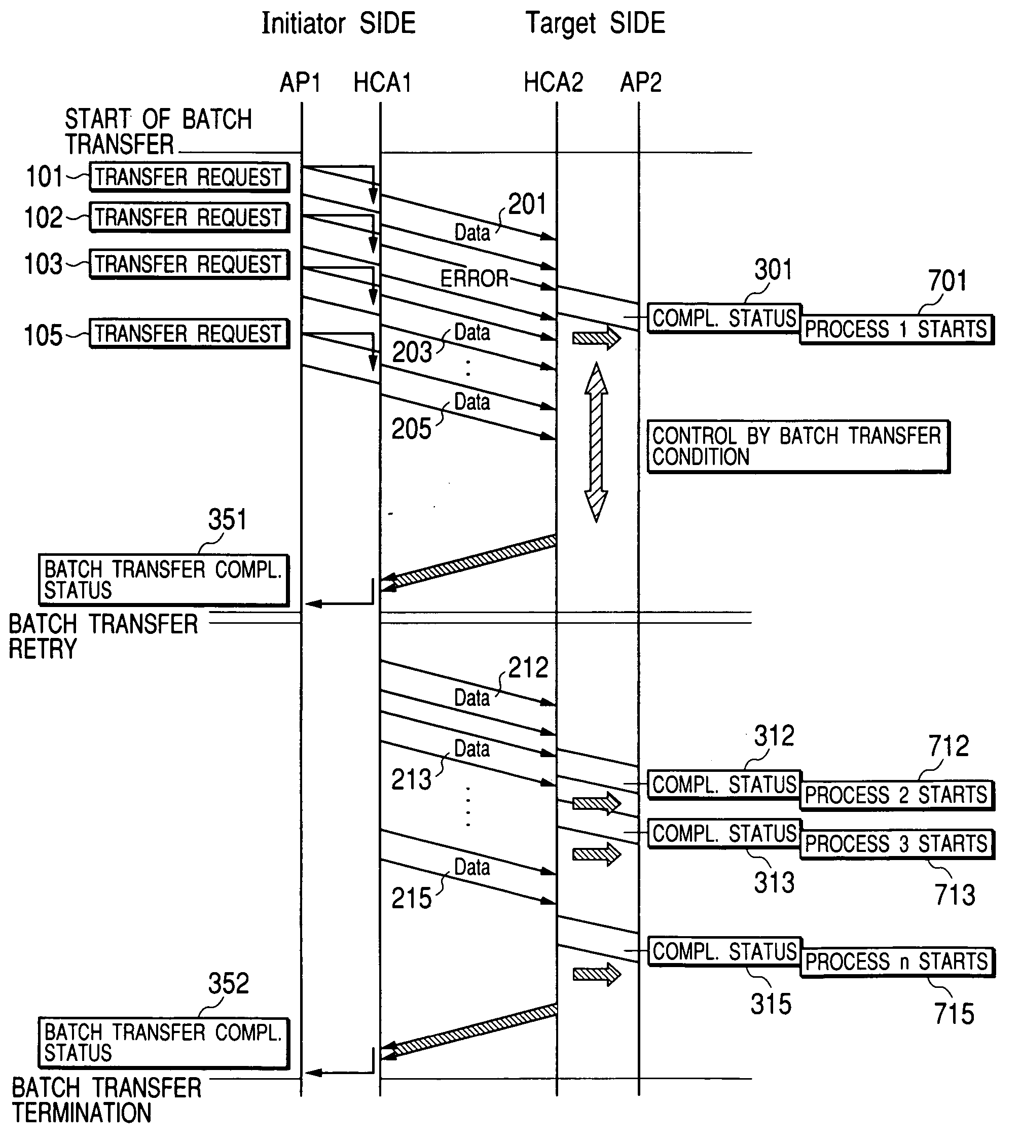
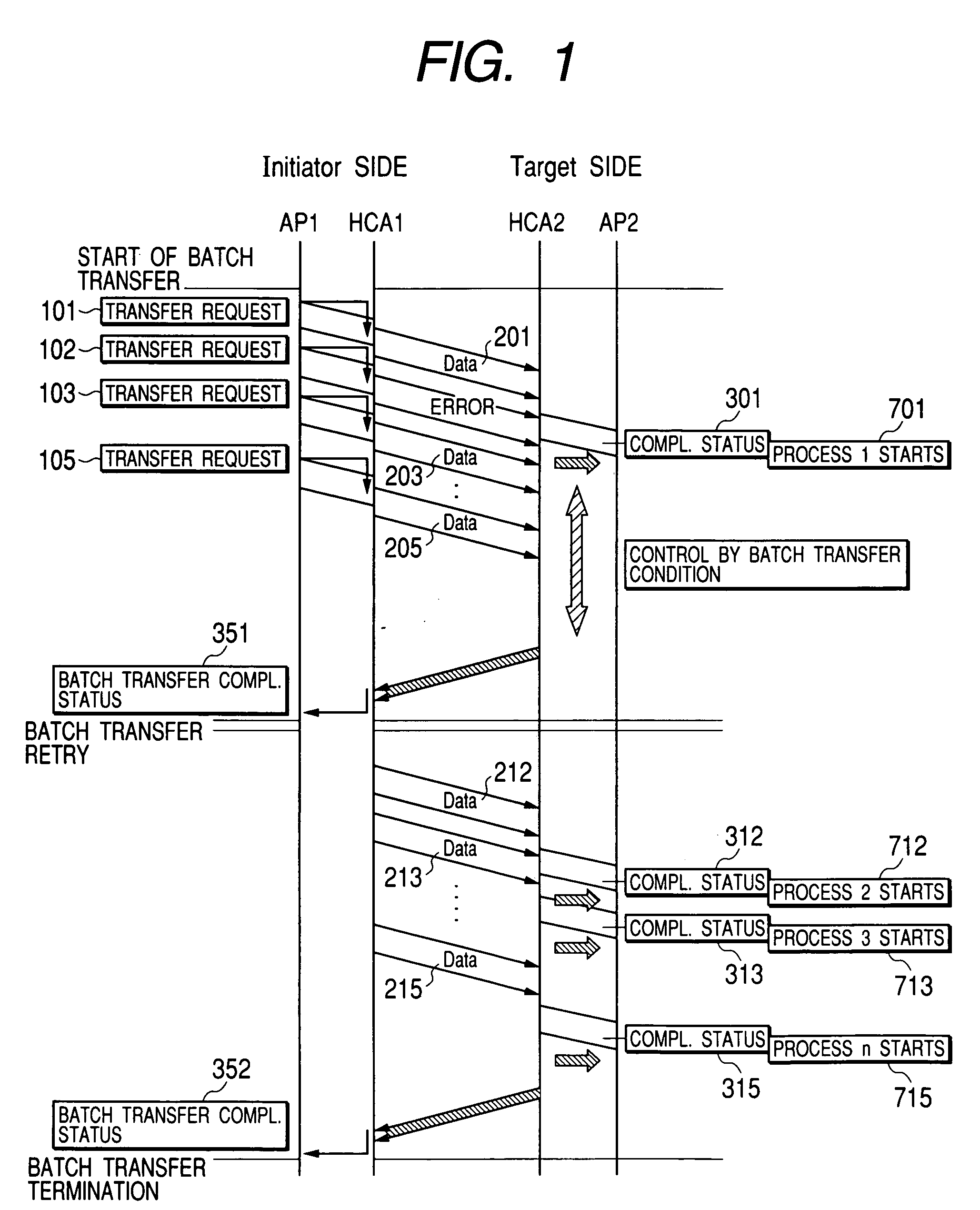
[0059] A preferred embodiment of the present invention is shown in FIGS. 1 and 8. In the data transfer method of the present invention, a plurality of logical records in a bock are batch transferred. Therefore, a plurality of transfer requests are serially stored in the send queue of the initiator, as is shown in FIG. 8. Each transfer request comprises a transfer ID which is uniquely determined per logical record to be transferred, a transfer operation code which defies the operation of the transfer request, the start address of a record buffer to which the record is to transferred, and buffer length. In FIG. 8, a transfer request 101 is an example of single-data transfer to a record buffer 89 and a transfer request 105 is an example of RDMA transfer to an area of destination of RDMA transfer 87. These transfer requests are defined as batch transfer requests.

[0060] In FIG. 8, a completion queue 39 which is used by the target to notify the initiator of completion of logical record r...

embodiment 2

[0065] In the high-speed data transfer method of the present invention, when logical records to be batch transferred are received, only the records that meet the batch transfer condition are selectively received. Even if there is dependency across the records to be batched transferred, it can be assured that the time sequence of received records remains the same as for those before being transferred. For example, if a receiving error is included in a logical record, a method in which logical records that are being batch transferred subsequent to that logical record are negated can be carried out. By this method, after all batch transfer requests are serially processed, the transfer of all non-received records is retried at a time. This method of the present invention prevents dependency disorder in received logical records and has an advantage that the initiator need not wait for the notification of transfer completion from the target, as the initiator in the traditional method does...

embodiment 3

[0066] The following gives a more detailed explanation of the batch transfer condition for use in the high-speed data transfer method of the present invention, using FIG. 9. FIG. 9 shows the structure of a packet for use in the high-speed data transfer method of the present invention. The packet consist of a routing header 441 having information about routing, a transport header 441 containing information about transport processing, a payload 443 containing logical record data, and a CRC 444 which is an error check code. The routing header contains the destination address of the initiator or the target, priority information of the packet, and packet length. The transport header contains a process operation code that defines transfer processing and a destination queue pair number, a sequence number of the packet, a batch transfer flag 450 which defines batch transfer operation, and a batch transfer condition field 451.

[0067] The batch transfer flag 450 indicates that the packet is b...


PUM


Abstract

The present invention provides a reliable and high-speed data transfer method that achieves a high transfer efficiency and a high application processing efficiency concurrently and a disk control unit (disk controller) using such a method. In reliable data transfer in which, when data is transferred from an initiator to a target, the data received by the target is checked for validity by using an error check code attached to the data, a transfer status indicating whether the data is valid is returned from the target to the initiator, and, if a transfer error occurring during the data transfer is detected by the transfer status, the initiator retries to transfer the data to the target, a data transfer method for logical records that are units of data transfer between the initiator and the target is disclosed. This method is characterized in that: when each logical record transferred by a transfer request issued by the initiator arrives correctly on the target, the target posts a completion status corresponding to the transfer request for the logical record to a completion queue existing in the target; a plurality of logical records in a block are batch transferred; the initiator confirms the transfer status at every batch transfer; and, for each logical record that meets a predetermined batch transfer condition, the target posts a completion status corresponding to the transfer request for the logical record to the completion queue existing in the target upon correct reception of the logical record.

Description

BACKGROUND OF THE INVENTION [0001] 1. Field of the Invention [0002] The present invention relates to a data transfer method for transferring data through a network in a highly reliable manner and at a high speed and to a disk control unit (disk controller) for controlling a plurality of disk drives. [0003] 2. Description of Related Art [0004] With enhancement of information communications infrastructures, there is a need for even higher processing capabilities' of information communications systems. As more miniaturized LSI integrated circuits have lately been evolved, in the current situation, system performance depends on the capability of data transfer between LSI devices. Therefore, study efforts are underway to enhance the IO system capability and augment its functions vigorously. Higher transfer speed has been achieved and communication protocol engines with a variety of transport functions have been developed. [0005] For example, InfiniBand transfer modes defined in InfiniBan...

Claims


Application Information

Patent Timeline
Patent Type & Authority Applications(United States)
IPC IPC(8): G06F3/06G06F13/00G06F13/10G06F13/38G06F13/42
CPCG06F3/0614G06F3/0655G06F13/42G06F3/0683G06F3/0656
Inventor HOSOYA, MUTSUMI
Owner GOOGLE LLC
Why Eureka
Try Eureka