Flying insect capture and monitoring system

a monitoring system and flying insect technology, applied in the field of capturing apparatuses for flying insects, can solve the problems of generating undesirable noises, affecting the safety of insects, and killing insects with electricity

Active Publication Date: 2007-07-26
CHUNWOO ENVIRONMENT SERVICE
View PDF12 Cites 63 Cited by
  • Summary
  • Abstract
  • Description
  • Claims
  • Application Information

AI Technical Summary

Benefits of technology

[0004] More particularly, the present invention intends to provide a flying insect capturing apparatus with birdlime, which is capable of monitoring the amount of captured flying insects and which can adjust the winding speed of the birdlime depending on the above captured amount.

Problems solved by technology

The insects captured by the capturing lamp are killed using electricity or they become stuck on birdlime.
Killing insects with electricity generates undesirable noises and produces unpleasant feelings to people nearby.
Thus, people such as homeowners tend to move away from using electricity to kill insects.
This is because the capacity of birdlime is limited and its adhesive strength becomes decreased due to dirt etc.
Of course, replacing the birdlime with a new one entails costs such as labor costs.
However, the birdlime became wound regardless of whether the flying insects were actually captured or not on the birdlime, thus resulting in unnecessary waste of the birdlime.

Method used


Image

  • Flying insect capture and monitoring system
  • Flying insect capture and monitoring system
  • Flying insect capture and monitoring system

Examples


first embodiment

[0069]FIG. 9 is a schematic diagram conceptually illustrating the remote monitoring system for insect control according to the present invention.

[0070] As illustrated therein, the remote monitoring system for insect control according to the embodiment of the invention includes the remote control unit 750, which is installed in a monitored subject site such as a building 710, 720 and 730, to keep a watch on the activities of insects and to collect data on them. It then transmits the previously collected data through a wireless network 760 or wired network 770 such as Internet or general telephone lines. The remote monitoring system also includes the central control unit 740, which analyzes and manages the transmitted data. The monitored subject site means a building where insects appears or is likely to appear, or any other predetermined spaces (e.g., public parks, places for loading freights, etc.), or an outer area of the building or the predetermined space.

[0071] The remote contr...

second embodiment

[0142]FIG. 21 is a diagram chart conceptually showing the remote monitoring system for insect control according to the

[0143] The difference between the first and second embodiments of the remote monitoring system of the present invention is that the central control unit 740 re-transmits the analysis result of the insect-related information to users of each building 710, 720 and 730 and / or to the service technician. More specifically, the service technician receives the analysis result of the insect-related information by using mobile communication terminal 70, such as a personal digital assistant (PDA) or a mobile phone, and performs insect control operation that is suitable for each monitored subject site.

[0144]FIG. 22 is a block diagram showing the central control unit 740 according to the second embodiment of the present invention.

[0145] The second embodiment comprises a receiving module 900 and a transmitting module 910 instead of the communication module of the first embodime...

third embodiment

[0149]FIG. 23 is a block diagram conceptually showing the remote monitoring system.

[0150] The difference between the second and third embodiments of the present invention is that insect-related information may be directly transmitted from remote control unit 750 to mobile communication terminal 70 in the third embodiment. Although mobile communication terminal 70 shown in FIG. 23 communicates with remote control unit 750 by wireless communication, mobile communication terminal 70 can also be configured to communicate with the remote control unit 750 via both wired and wireless communications. In the third embodiment of the present invention, the service technician may receive an instruction to move to a subject site from the remote control unit 750, which is installed at the site, or from the central control unit 740. He / she can also receive insect-related information from both.

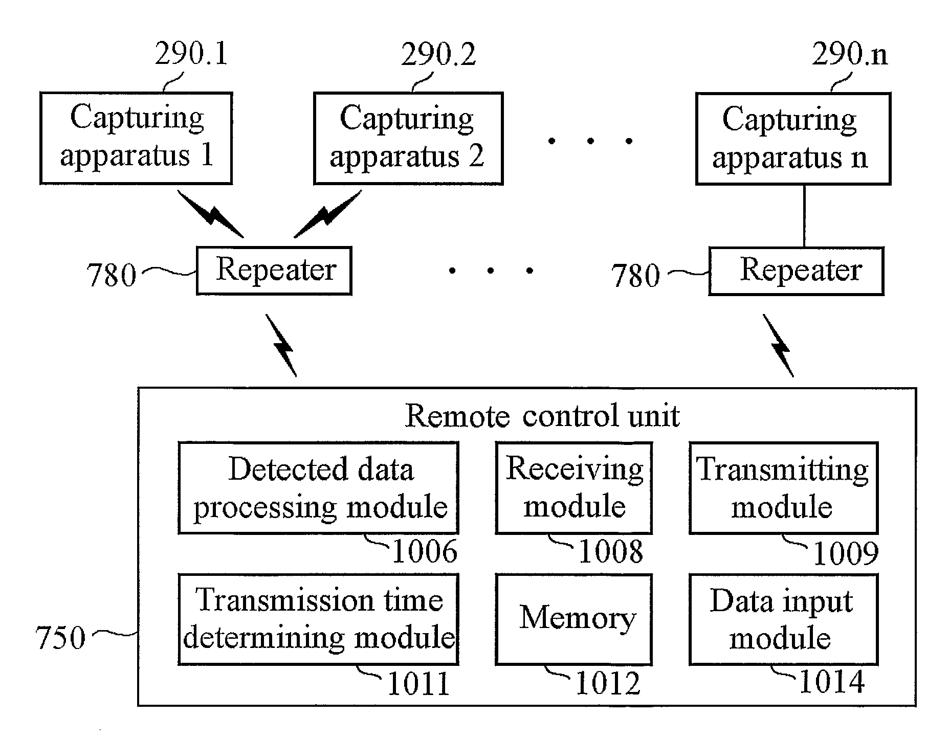
[0151]FIG. 24 is a block diagram conceptually showing the remote control unit 750 according to the third ...


PUM


Abstract

There is provided a capturing apparatus for capturing flying insects, comprising: a UV lamp; a birdlime cartridge; a birdlime configured to be wound to the birdlime cartridge; and a means for winding the birdlime at a variable speed.

Description

TECHNICAL FIELD [0001] The present invention generally relates to a capturing apparatus for capturing flying insects, and more particularly to a capturing apparatus with a new structure for capturing flying insects and an apparatus for determining the amount of the captured flying insects so as to utilize the information gathered thereby for insect control. BACKGROUND ART [0002] Conventionally, a capturing lamp has been widely used in order to capture flying insects such as mosquitoes and flies. The insects captured by the capturing lamp are killed using electricity or they become stuck on birdlime. Killing insects with electricity generates undesirable noises and produces unpleasant feelings to people nearby. Thus, people such as homeowners tend to move away from using electricity to kill insects. In case of using birdlime, the birdlime has to be regularly replaced with a new one. This is because the capacity of birdlime is limited and its adhesive strength becomes decreased due to...

Claims


Application Information

Patent Timeline
Patent Type & Authority Applications(United States)
IPC IPC(8): A01M1/04A01M1/14A01M1/12A01M1/10
CPCA01M1/145A01M1/16A01M2200/012Y10S43/00
Inventor CHYUN, CHAN HYUK
Owner CHUNWOO ENVIRONMENT SERVICE
Why Eureka
Try Eureka