
Swagable high-pressure cable connectors having improved sealing means

a high-pressure cable and connector technology, applied in the direction of power cables, cables, coupling device connections, etc., can solve the problems of undesirable environmental and safety consequences

Active Publication Date: 2007-07-26
NOVINIUM LLC
View PDF56 Cites 41 Cited by
  • Summary
  • Abstract
  • Description
  • Claims
  • Application Information

AI Technical Summary

Benefits of technology

"The patent describes a high-pressure connector for an electrical power cable section. This connector is designed to contain a fluid within the space between the cable's conductor and insulation jacket, while keeping the pressure above atmospheric but below the elastic limit of the insulation jacket. The connector has a housing with a chamber that is in fluid communication with the void space between the conductor and insulation jacket. The housing has a deformable material that securely attaches to the insulation jacket to confine the fluid at the residual pressure. The connector also has an engagement member that helps hold the parts together. The technical effect of this invention is to provide a reliable and safe way to contain fluids in high-pressure electrical power cables."

Problems solved by technology

However, leak-free performance is still highly desirable since there remains some chance of damage to the splice or termination from even a minor leak.
Furthermore, any fluid that leaks from the connector would not be available to treat and restore the cable dielectric properties, and there may also be undesirable environmental and safety consequences of such a leak.

Method used


Image

  • Swagable high-pressure cable connectors having improved sealing means
  • Swagable high-pressure cable connectors having improved sealing means
  • Swagable high-pressure cable connectors having improved sealing means

Examples


examples

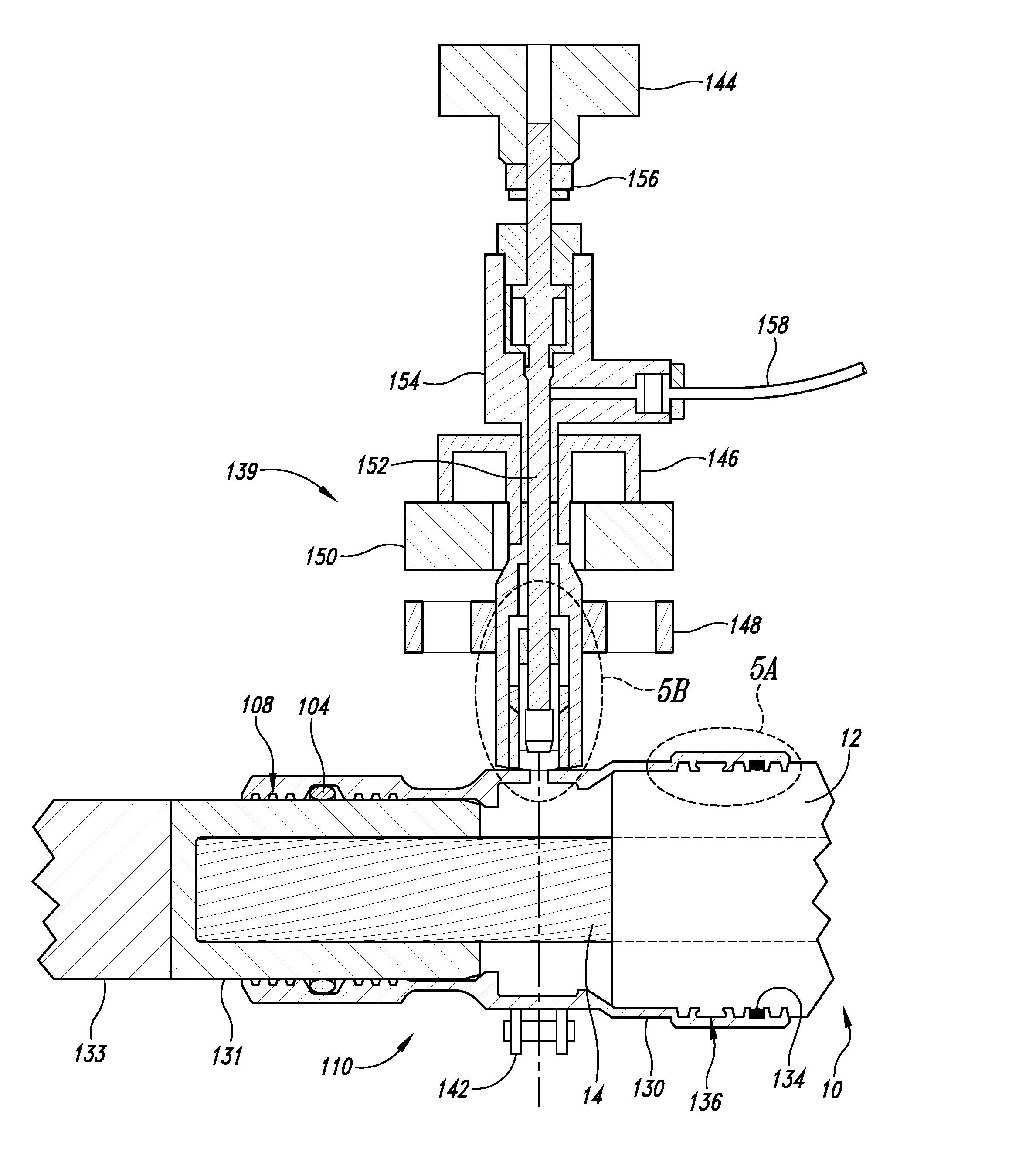
[0094] The following terminal high-pressure connectors having various housing sealing geometries with respect to the insulation jacket of a cable section were evaluated for leakage under substantial thermal cycling conditions. Each test connector employed comprised a housing having a threaded injection port 182 at one end thereof, as illustrated in cross-sectional view in FIG. 15, in this case the conductor shield 13 being shown. Five different housing sealing geometries were tested (shown in FIGS. 15, and 15A-15D), as follows: [0095] (I) Acme thread-shaped grooves 138 in housing 180 (see FIG. 15 which uses a broken line to identify the insulation swaging region of the housing). [0096] (II) Square grooves 132 in housing 184 (see FIG. 15A showing detail of the insulation swaging region). [0097] (III) Trapezoidal grooves 136 in combination square grooves 132 in housing 186 (see FIG. 15B showing detail of the insulation swaging region) corresponding to the trapezoidal groove 136 illust...


PUM

PropertyMeasurementUnit
residual pressureaaaaaaaaaa
temperatureaaaaaaaaaa

Abstract

A high-pressure connector for an electrical power cable section having a central stranded conductor encased in a polymeric insulation jacket and having an interstitial void volume in the region of the stranded conductor, the high-pressure connector being suited for confining a fluid within the interstitial void volume at a residual pressure above atmospheric, but below the elastic limit of the polymeric insulation jacket, the high-pressure connector comprising a housing having a wall defining an interior chamber configured to be in fluid communication with the interstitial void volume and an end portion sized to receive the insulation jacket within the interior chamber and to overlap at least a portion of the insulation jacket at an end thereof with the cable section extending from the housing end portion and at least a portion of the stranded conductor positioned within the interior chamber. The housing wall of the housing end portion has an engagement portion comprised of a swagable material to secure the housing wall to the insulation jacket in fluid-tight sealed engagement therewith upon inward swaging of the engagement portion of the housing wall of the housing end portion to the insulation jacket to confine the fluid at the residual pressure within the interior chamber and the interstitial void volume. The housing includes at least one axially-projecting engagement member located within the interior chamber at the engagement portion of the housing wall of the housing end portion.

Description

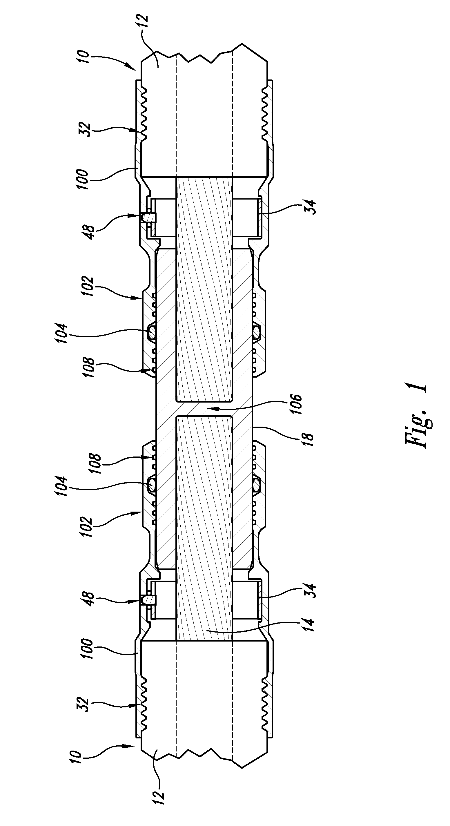
CROSS REFERENCE TO RELATED APPLICATION(S) [0001] This application claims priority benefit of provisional application Ser. No. 60 / 761,099 filed Jan. 23, 2006, which is incorporated herein in its entirety.FIELD OF THE INVENTION [0002] The present invention relates to a swagable high-pressure connector especially suited for injecting a dielectric enhancement fluid into the interstitial void volume of an electrical power cable at elevated pressures and confining the fluid therein at a similar elevated pressure. DESCRIPTION OF THE RELEVANT ART [0003] Swagable high-pressure connectors were previously described in United States Patent Application Publication No. US 2005 / 0191910. An example of a dual-housing, swagable high-pressure splice connector, assembled from two identical swagable high-pressure terminal connectors, is illustrated in FIG. 8 of this publication and is reproduced herein as FIG. 1. The housing 100 is swaged to the insulation jacket 12 such that teeth 32 penetrate the latt...

Claims


Application Information

Patent Timeline
Patent Type & Authority Applications(United States)
IPC IPC(8): H01B9/06
CPCH01R13/5205H01R13/5216H01R4/22H01R4/64
Inventor BERTINI, GLEN J.THEIMER, ANTHONY ROY
Owner NOVINIUM LLC
Learn More