Beam deflector and scanning microscope

a beam deflector and scanning microscope technology, applied in the field of beam deflector and scanning microscope, can solve the problems of large loss of excitation light or detection light, and achieve the effect of preventing the transfer of structural nois

Inactive Publication Date: 2007-07-26
LEICA MICROSYSTEMS CMS GMBH
View PDF15 Cites 5 Cited by
  • Summary
  • Abstract
  • Description
  • Claims
  • Application Information

AI Technical Summary

Benefits of technology

[0021] Preferably, means for preventing the transfer of structural noise from the housing to the rest of the scanning microscope are provided. For t...

Problems solved by technology

Neutral beam splitters have the disadvantage that a great deal of exci...

Method used


Image

  • Beam deflector and scanning microscope
  • Beam deflector and scanning microscope

Examples


Embodiment Construction

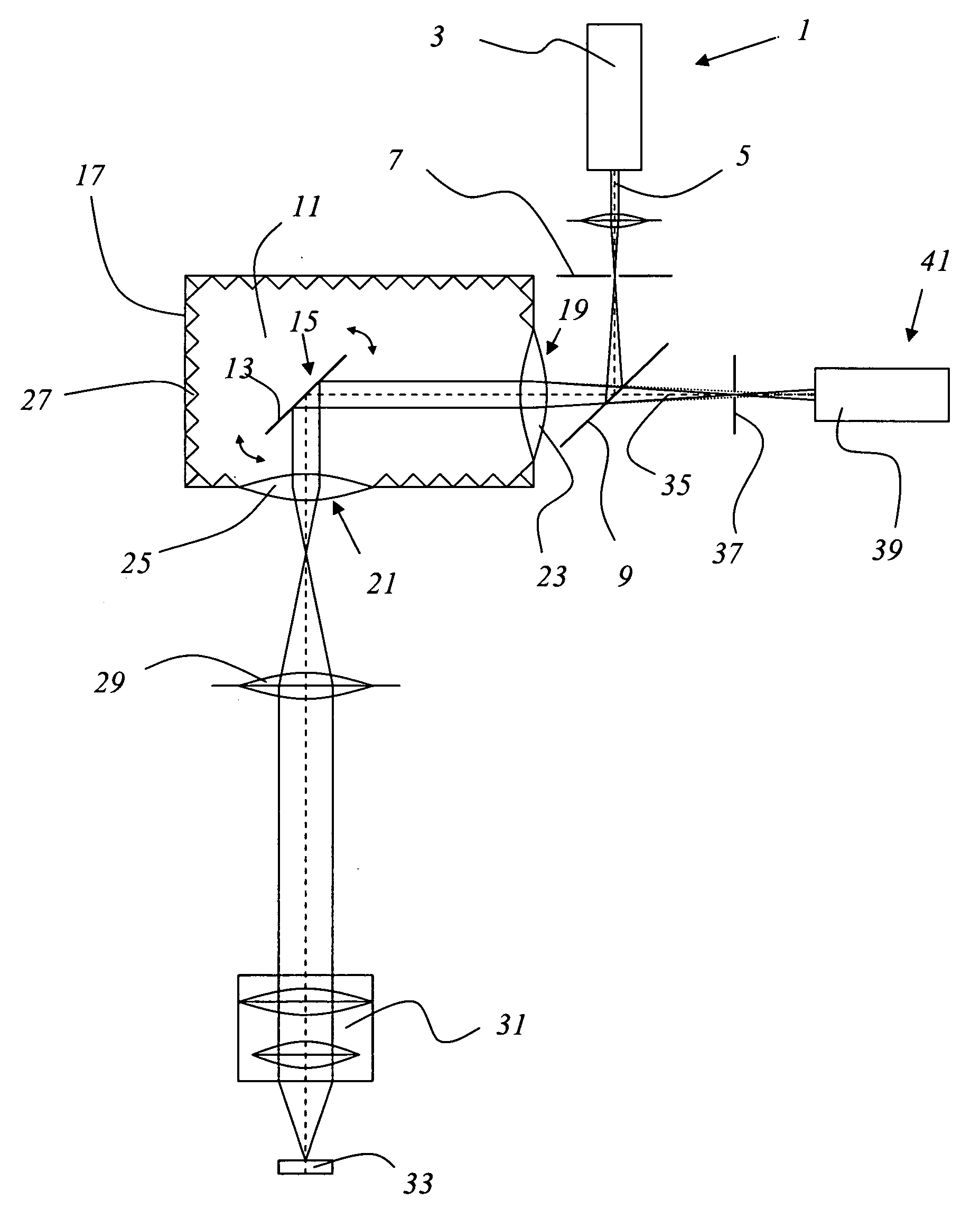
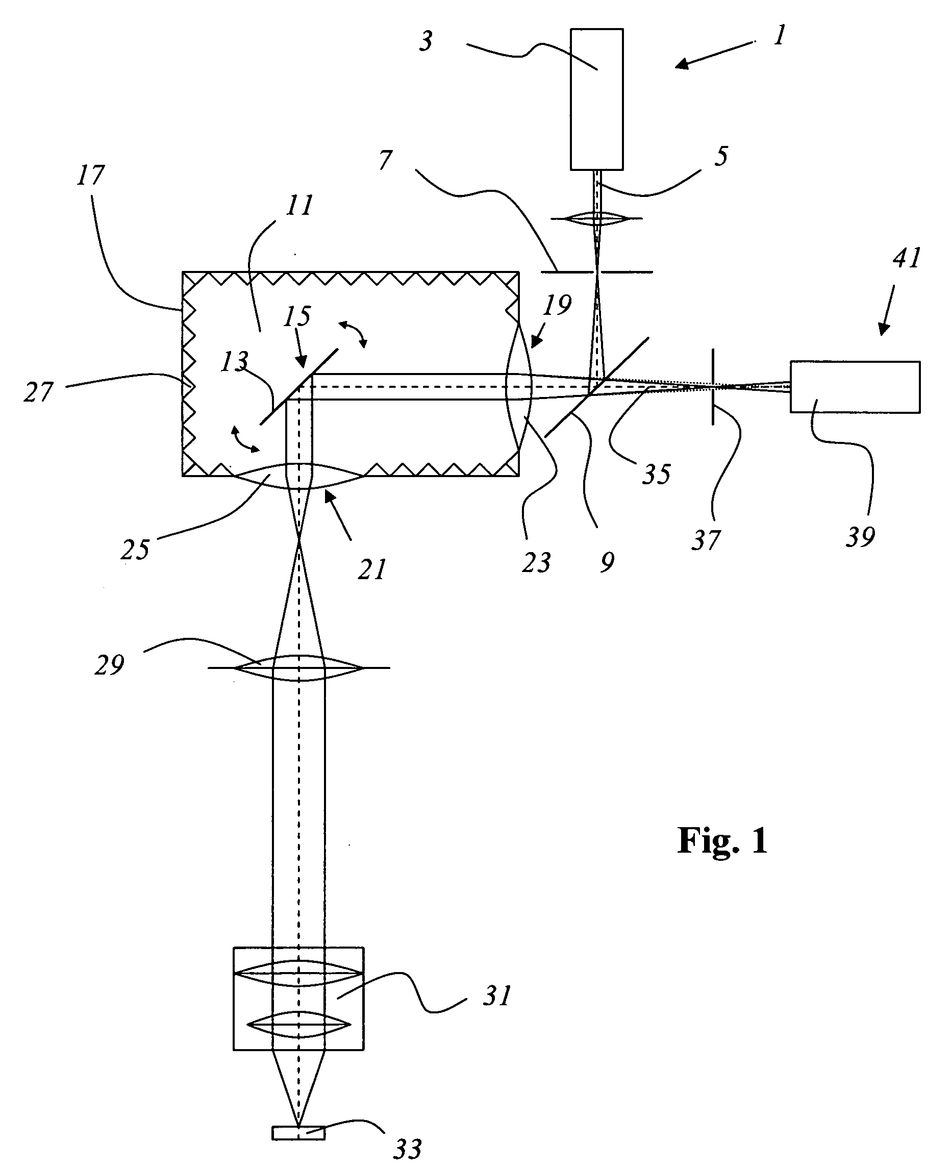
[0027]FIG. 1 shows a scanning microscope according to the invention that is implemented as a confocal scanning microscope. The scanning microscope exhibits a first illumination light source 1 that is implemented as a multiline laser 3 and that generates an illumination light beam 5. The illumination light beam 5 passes through the illumination pinhole aperture 7 and is subsequently directed via a primary beam splitter 9 that is implemented as a dichroic filter to a beam deflector 11 that comprises a cardanically mounted scanning mirror 13 as the movable deflector 15.

[0028] The beam deflector 13 exhibits a soundproof housing 17 in which is arranged the movable deflector 15 for adjustable deflection of the illumination light beam 5. The soundproof housing 17 exhibits an entrance window 19 and an exit window 21 in relation to the illumination light beam 5. The entrance window 19 is implemented as a lens 23 that collimates the illumination light beam 5. The exit window 21 comprises the...


PUM


Abstract

A scanning microscope comprises a beam deflector with at least one movable deflector to adjust the deflection of a light beam. The scanning microscope is characterized in that the movable deflector is positioned in a largely soundproof housing with one entrance window and/or one exit window.

Description

RELATED APPLICATIONS [0001] This application claims priority to German patent application number DE 10 2004 049 437.1, filed Oct. 19, 2004, which is incorporated herein by reference in its entirety. BACKGROUND OF THE INVENTION [0002] The invention relates to a beam deflector with at least one movable means of deflection to adjust the deflection of a light beam. [0003] The invention further relates to a scanning microscope with at least one movable means of deflection to adjust the deflection of a light beam. SUMMARY OF THE INVENTION [0004] In scanning microscopy, a sample is illuminated with a light beam to observe the reflection and fluorescent light emitted by the sample. The focus of an illumination light beam is moved in an object plane with the help of a maneuverable beam deflector, generally by tipping two mirrors, whereby the axes of deflection are usually positioned perpendicular to each other, so that one mirror deflects in the x-direction and the other in the y-direction. ...

Claims


Application Information

Patent Timeline
IPC IPC(8): G02B26/08
CPCG02B26/0816G02B21/0048
Inventor BIRK, HOLGERFEHRER, DIRK-OLIVERGOLDNER, MICHAEL
Owner LEICA MICROSYSTEMS CMS GMBH
Why Eureka
Try Eureka