Electrical connector

Inactive Publication Date: 2007-07-26
HON HAI PRECISION IND CO LTD
View PDF19 Cites 0 Cited by
  • Summary
  • Abstract
  • Description
  • Claims
  • Application Information

AI Technical Summary

Benefits of technology

[0007]Accordingly, an object of the present invention is to provide an e

Problems solved by technology

However, in the electrical connector abovementioned, the cover is conventional not accurately locating on the housing, and engaged with the housing by a interferential engagement.
After a long time, the engagement between the cover and the housing is prone to loose, hence the housing is easy to slide in relative

Method used


Image

  • Electrical connector
  • Electrical connector
  • Electrical connector

Examples


Embodiment Construction

[0014]Reference will now be made to the drawings to describe the present invention in detail.

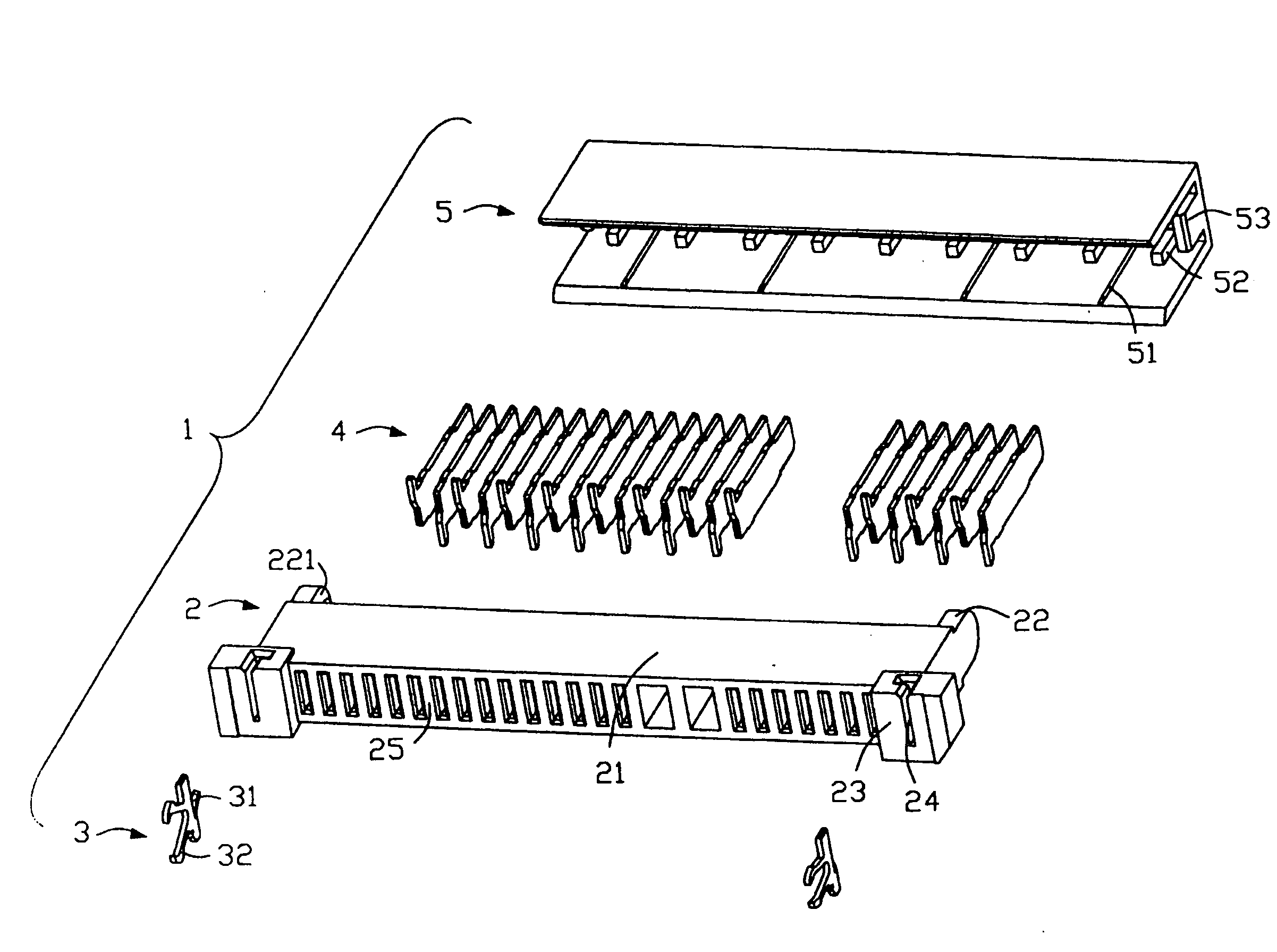
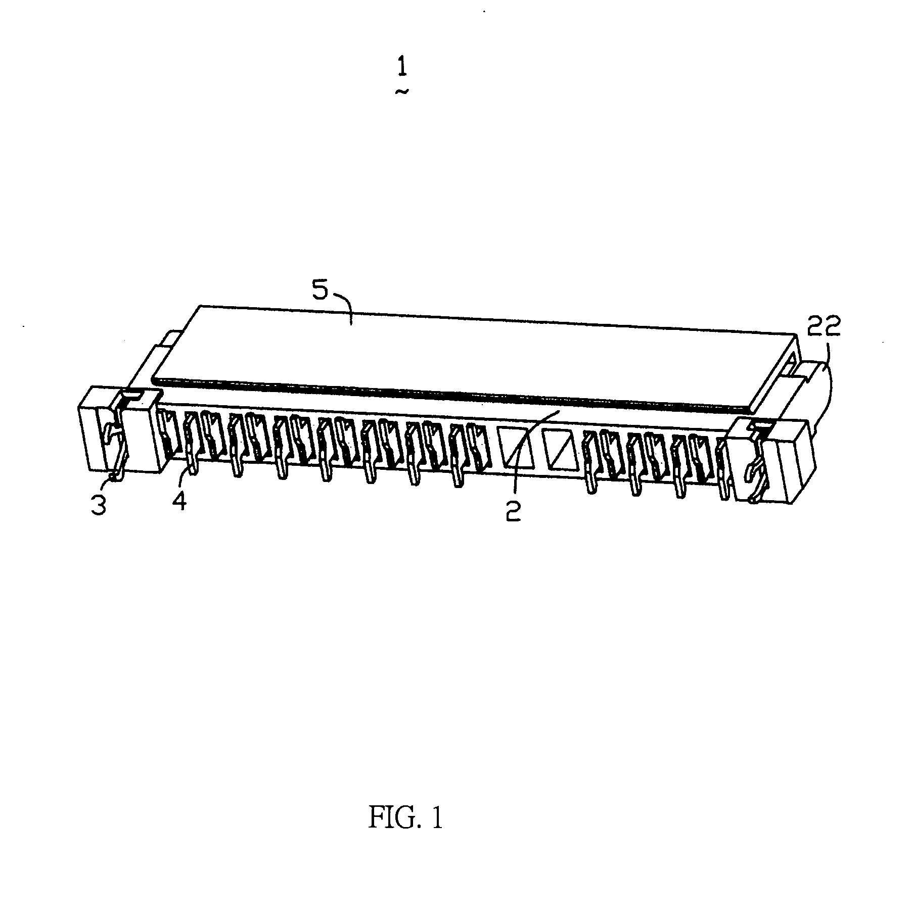
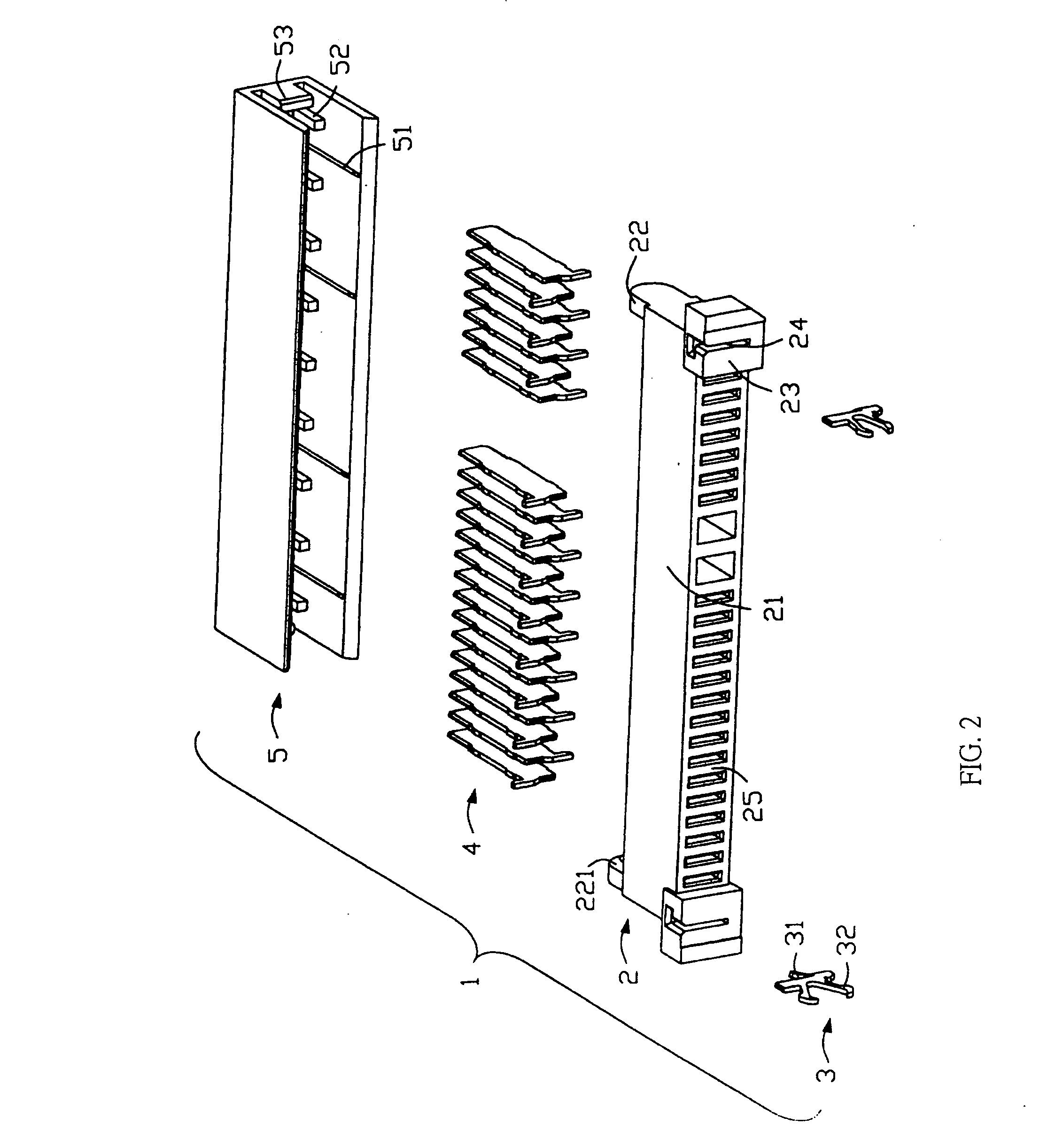
[0015]Referring to FIGS. 1-2, an electrical connector 1 in accordance with the preferred embodiment of the present invention provided for electrically connecting a application to a PCB includes a generally rectangular insulative housing 2, a pair of anchoring hooks 3, a multiplicity of terminals 4 received in the housing 2 and a cover 5 attached on the housing 2.

[0016]The housing 2 includes a rectangular base portion 21. The base portion 21 defines a pair of locating portions 22 on two ends thereof which define a slant surface 221 on an end thereof respectively. In addition, the base portion 21 defines a pair of rectangular base substrates 23 on two ends thereof and each base substrate 23 defines a recess 24 on a bottom surface thereof. The base portion 21 further defines a plurality of passageways 25 for receiving the terminals 4 therein between the two locating projections 22.

[0017]The anc...


PUM


Abstract

An electrical connector (1) comprises an insulative housing (2) comprising plurality of passageways (25) thereon, a plurality of electrical terminals (4) received in the housing (2), a cover (5) mounted on the housing (2), wherein the cover (5) includes a number of formable members (52) extending from an inner sidewall thereof for supporting the housing (2), hence preventing the housing (2) from destroying terminals (4).

Description

BACKGROUND OF THE INVENTION[0001]1. Field of the Invention[0002]The present invention relates to the art of electrical connectors, and more particularly to an electrical connector provided for connecting an electrical applications to a printed circuit board (PCB).[0003]2. Description of the Prior Art[0004]Electrical connectors are widely used in the connector industry for electrically connecting applications to printed circuit boards (PCBs) in personal computer or other consumer electrical equipments. Conventionally, an electrical connector mainly comprises an insulative housing, a multiplicity of terminals received therein, an anchoring hook, a cover mounted on the housing. The housing defines a plurality of receiving passageways for receiving terminals therein. When assembled, the terminals are inserted into the passageways of the housing, and then the cover is mounted above the housing. In this case, the electrical connector is usually positioned on the printed circuit board by a...

Claims


Application Information

Patent Timeline
IPC IPC(8): H01R13/44
CPCH01R12/57H01R13/04H01R13/5025Y10S439/94H01R43/18H01R12/7029H01R43/0263
Inventor WU, TSU-YANGCHEN, SHENG-KO
Owner HON HAI PRECISION IND CO LTD
Why Eureka
Try Eureka