Transmitter-receiver comprising an electronic chip

Active Publication Date: 2020-06-11
THE SWATCH GRP RES & DEVELONMENT LTD
View PDF0 Cites 0 Cited by
  • Summary
  • Abstract
  • Description
  • Claims
  • Application Information

AI Technical Summary

Benefits of technology

[0007]One advantage of the present invention is that with the proposed arrangement in the transmitter-receiver according to the invention, the same radio frequency receiving channel can be used as that used in a conventional radio frequency signal transmitter-receiver, to demodulate signals from another optical or sound transmission medium.
[0008]Moreover, thanks to the presence in the transmitter-receiver of a second frequency synthesiser configured such that it synthesises a modulated low-frequency signal supplied by the auxiliary output terminal, full-duplex communication can take place in different transmission media.
[0009]The second frequency synthesiser is typically a low-frequency frequency synthesiser. The centre frequency of the modulated signal supplied by the second frequency synthesiser is equal to the value of the intermediate frequency.
[0010]Another advantage of the transmitter-receiver according to the invention is that in the case of a disrupted radio frequency medium, secure, confidential and effective communication can still take place over a different medium from the radio frequency medium. Such a disruption of the radio

Problems solved by technology

However, such mobile communication devices are not capable of sharing the same processing means for processing signals originating from different transmission media.
Furthermore, such device

Method used


Image

  • Transmitter-receiver comprising an electronic chip

Examples


Example

[0016]In the following description, all of the components of the frequency synthesisers, in particular in a transmitter-receiver of radio frequency signals and of signals from a frequency domain that is different from the radio frequency domain, which are well known to a person skilled in the art in this technical field, are only described in a simplified manner.

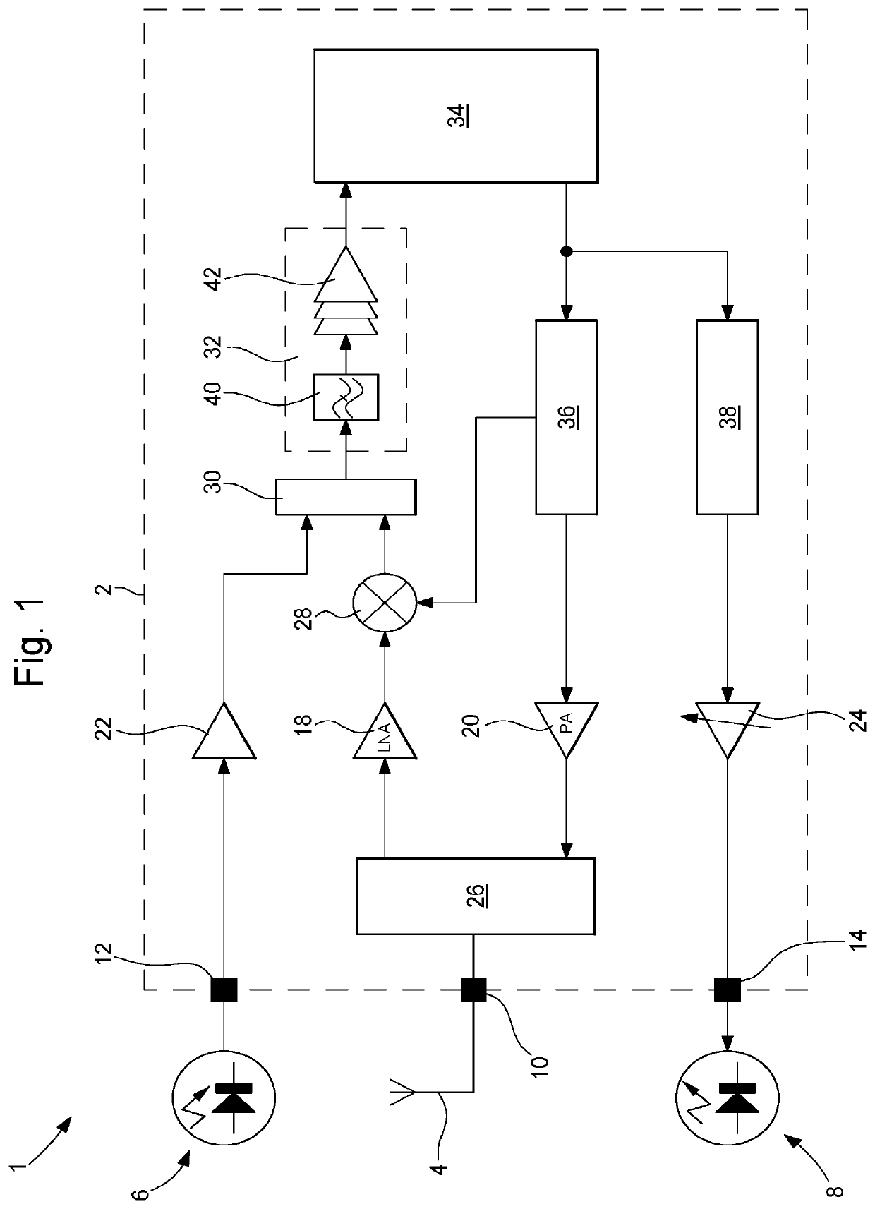
[0017]FIG. 1 shows a general view of a transmitter-receiver 1. The transmitter-receiver 1 comprises an electronic chip 2. In a normal operating mode, the transmitter-receiver 1 further comprises an antenna 4 for transmitting and receiving radio frequency signals at a carrier frequency of about 2.4 GHz, means 6 for receiving an optical, infrared, sound or ultrasound signal, and means 8 for transmitting an optical, infrared, sound or ultrasound signal. In the example embodiment shown in FIG. 1, the receiving means 6 are formed by an infrared diode for receiving an infrared signal, and the transmitting means 8 are formed by an ...


PUM


Abstract

A transmitter-receiver includes an electronic chip a mixer for mixing the frequency of a received radio frequency signal with that of an oscillating signal supplied by a first frequency synthesizer in, a switch having two inputs connected to an output of the mixer and to an auxiliary input terminal, a filter and gain stage connected to the output of the switch, and a modulator-demodulator connected to the output of the filter and gain stage. The first frequency synthesizer is connected between the output of the modulator-demodulator and radio frequency input and output terminal, and configured to supply a frequency-modulated signal to the radio frequency input and output terminal. The electronic chip further includes a second frequency synthesizer connected between the output of the modulator-demodulator and an auxiliary output terminal, and configured to synthesize a modulated low-frequency signal supplied by the auxiliary output terminal, whereby the center value of the low frequency is equal to the value of the intermediate frequency.

Description

TECHNICAL FIELD OF THE INVENTION[0001]The invention relates to a transmitter-receiver of radio frequency signals and of signals from a frequency domain that is different from the radio frequency domain, such as optical, infrared, sound or ultrasound signals, the transmitter-receiver including an electronic chip.PRIOR ART[0002]Radio frequency, optical or ultrasonic communication systems or systems using any other transmission medium generally implement only a single communication means for transmitting or receiving data signals. In other words, in such systems, a single transmission medium is generally used by each system.[0003]The design of mobile communication devices is known, which design procures the possibility of receiving radio frequency and / or optical and / or ultrasound signals, in other words which devices are capable of receiving signals originating from at least two different transmission media. However, such mobile communication devices are not capable of sharing the same...

Claims


Application Information

Patent Timeline
IPC IPC(8): H04B14/06H04W88/06H04B1/00
CPCH04B14/06H04W88/06H04B1/005H04B1/40H04B10/40H04L5/14H04B1/406
Inventor CASAGRANDE, ARNAUDSCORDILIS, THIERRYDE ROSA, LUCAGORISSE, JEANAREND, JEAN-LUC
Owner THE SWATCH GRP RES & DEVELONMENT LTD
Why Eureka
Try Eureka