
Electrical terminal block

Inactive Publication Date: 2007-07-26
PHOENIX CONTACT GMBH & CO KG
View PDF5 Cites 7 Cited by
  • Summary
  • Abstract
  • Description
  • Claims
  • Application Information

AI Technical Summary

Benefits of technology

[0013]Therefore, an aspect of this invention is to embody and develop an electrical terminal block consisting of several base terminals and several connectors such that reliable mechanical fixing of the connectors to the base terminals can be ensured. Moreover, the number of interconnected base terminals and number of connectors combined with one another into a connector block is freely selectable. A connector is made available which alone or together with other connectors can be reliably fixed on the base terminal or several base terminals.
[0019]The mechanical connection between the fixing device made in the fixing base terminal and the fixing mechanism made on the fixing cover can be executed as a catch connection. Preferably, this connection is made as a screw connection, for which the fixing device or devices in the terminal housing of the fixing base terminal is or are made as a threaded insert and the fixing covers have a screw receiver and a screw as the fixing mechanism. This ensures reliable and permanent mechanical fixing of the fixing cover, and thus of the connector, on the fixing base terminal by a corresponding screw being inserted into the screw receiver on the fixing cover and then being screwed into the threaded insert in the fixing base terminal.

Problems solved by technology

Since a special tool is necessary for stripping the electrical conductor, and since stripping is relatively time-consuming, for many years electrical terminals have also been used to which electrical conductors can be connected without prior stripping.
In known electrical series terminals, the base terminal has two receptacles, but the connector can only be plugged into the outer of the two receptacles, since otherwise the connector can no longer be fixed on the base terminal with the fixing element.
If the fixing element is lost, it is possible that a connector can be unintentionally pulled out of the base terminal.

Method used


Image

  • Electrical terminal block
  • Electrical terminal block
  • Electrical terminal block

Examples


Embodiment Construction

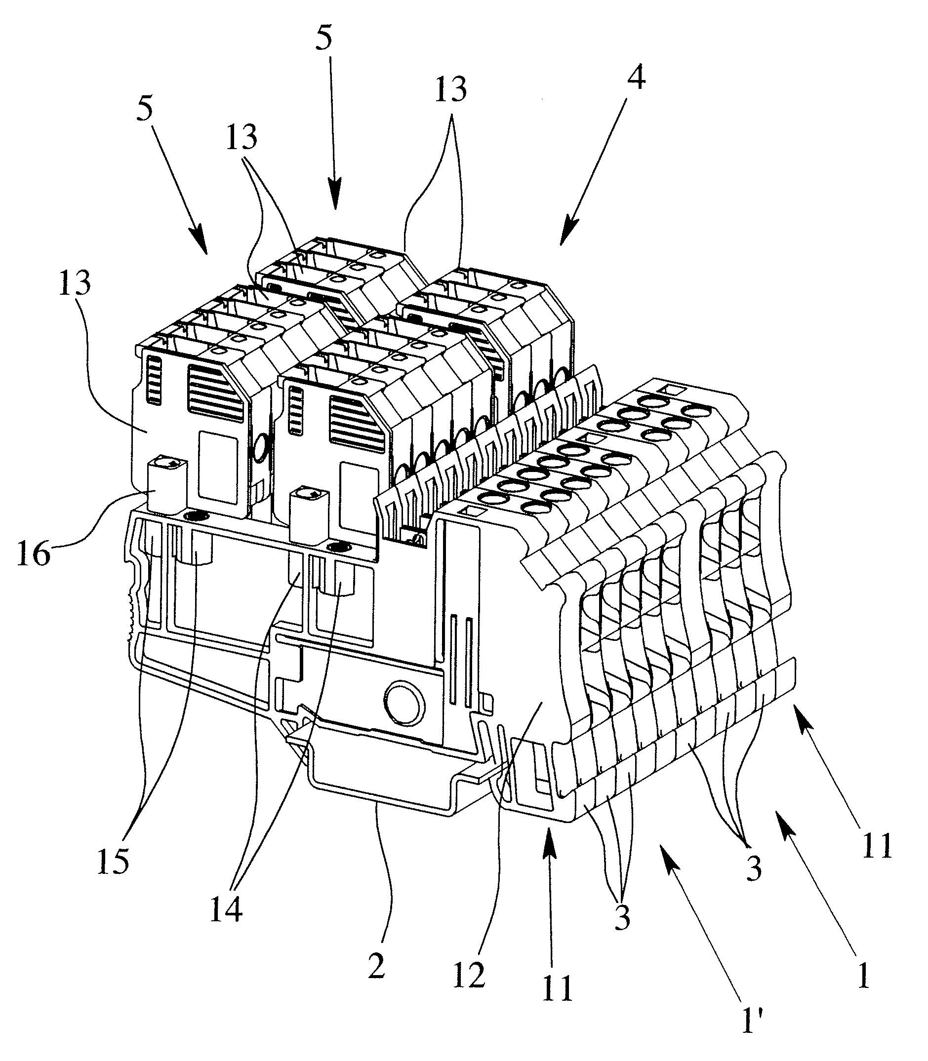
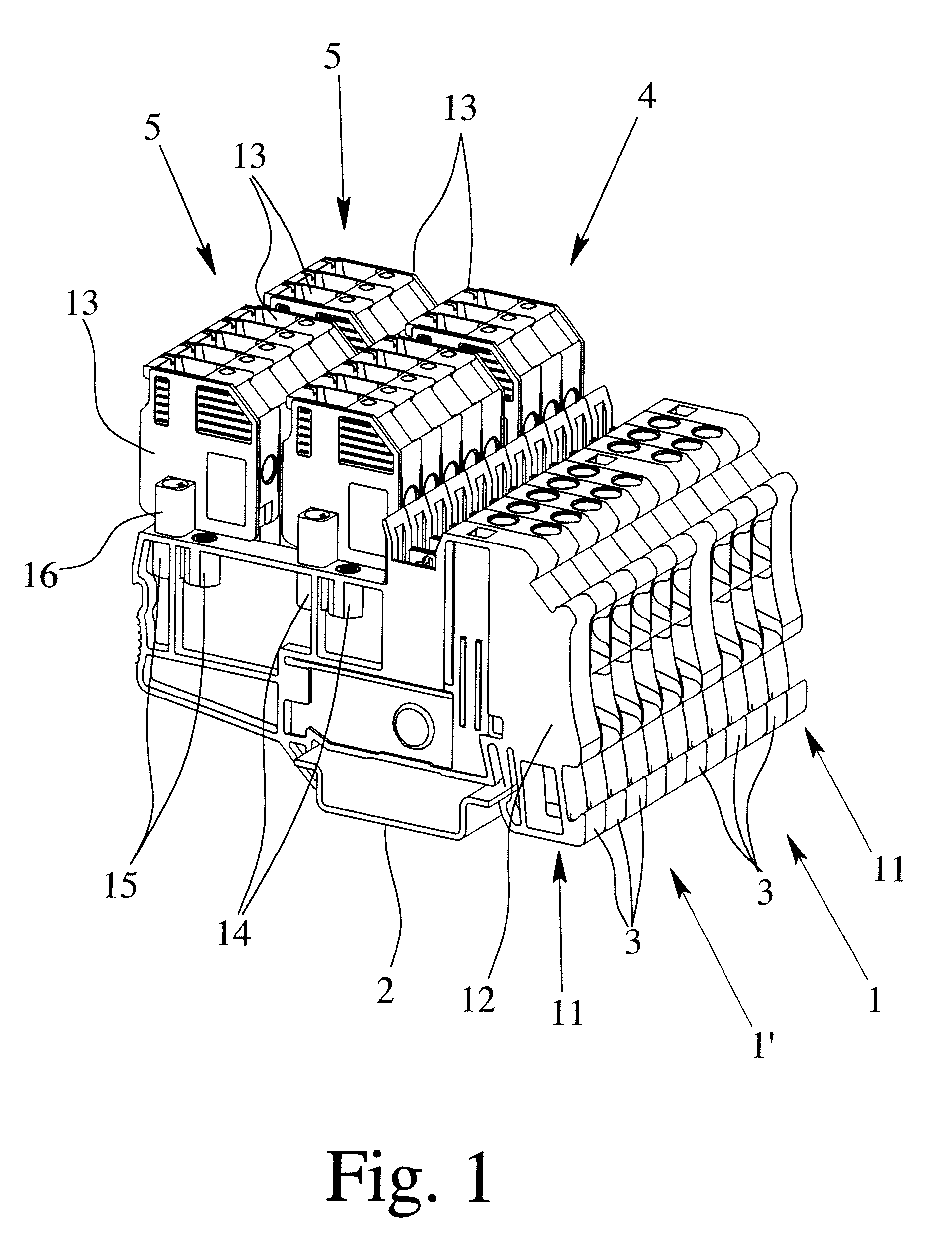
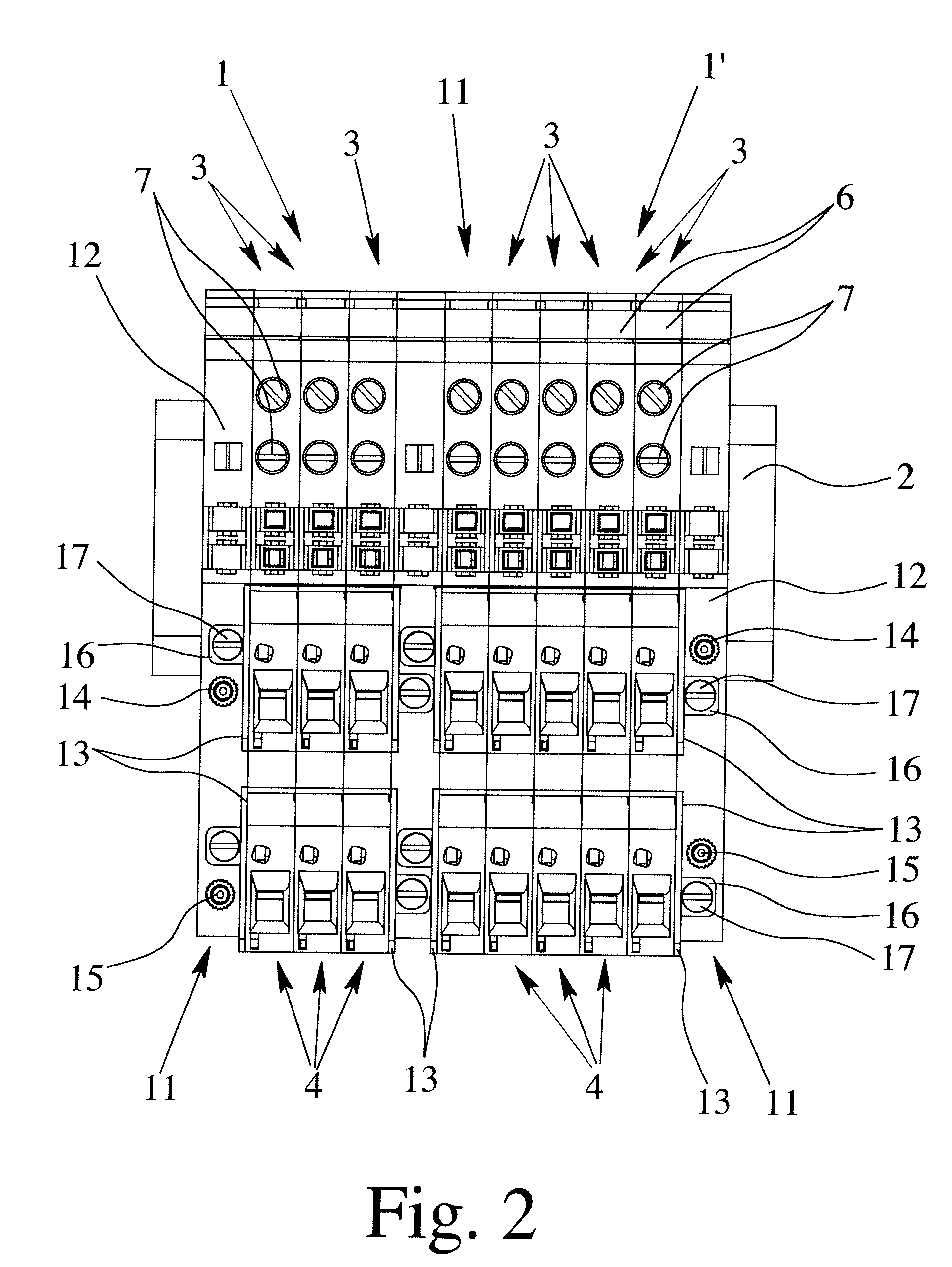
[0032]FIGS. 1 & 2 each show two electrical terminal blocks 1, 1′ that are located next to one another on the mounting rail 2. The two terminal blocks 1, 1′ consist of three and five base terminals 3 located next to one another and one double display each, i.e. six and ten connectors 4, 5, two connectors 4, 5 each being plugged onto a base terminal 3. To fix the base terminals 3 on the mounting rail 2, corresponding catch elements are formed in the base of the base terminal 3, as known.

[0033]Best seen inFIG. 2, the base terminals 3 each have a terminal housing 6 made of an insulating material and two conductor terminal elements located therein. The conductor terminal elements, which are made as screw terminals, but likewise can alternatively be made as tension spring terminals, leg spring terminals or as insulating piercing terminals, are each connected to one receptacle at a time onto which the connectors 4, 5 are plugged via conductor bars, not shown. FIG. 2 shows the individual cl...


PUM


Abstract

An electrical terminal block, especially for locking onto a mounting rail, has a plurality of adjacent base terminals and connectors. Each base terminal has a terminal housing, with at least one conductor terminal element and at least one receptacle electrically connected to the conductor terminal element or at least two interconnected receptacles. The individual connectors have a connector housing, with at least one conductor terminal element and a plug-in contact electrically connected to the conductor terminal element. The individual connectors can be plugged onto the individual terminal housings. Reliable mechanical fixing of the connectors on the base terminals is ensured since each outer side of the base terminals has a fixing device on the terminal housing. Sides of adjacent connectors have a fixing cover with a fixing mechanism corresponding to the fixing device, so that the connectors can be mechanically connected to the fixing base terminals via the fixing covers.

Description

BACKGROUND OF THE INVENTION[0001]1. Field of the Invention[0002]The invention relates to an electrical terminal block, especially for locking onto a mounting rail. The invention particularly relates to electrical terminal blocks having a plurality of base terminals located next to one another and a plurality of connectors located next to one another and mounted on the base terminals.[0003]2. Description of Related Art[0004]Electrical series terminals have been known for decades and are being used in the millions in the wiring of electrical systems and devices. Series terminals are generally locked onto mounting rails that are often located in multiples in a control cabinet. The series terminals are generally made as connecting terminals so that they have at least two conductor terminal elements that are electrically connected to one another via an electrically conductive connecting bar, known as the conductor bar. In addition to this basic type of series terminals, there are many di...

Claims


Application Information

Patent Timeline
IPC IPC(8): H01R4/48
CPCH01R9/2491H01R9/2616H01R9/26
Inventor BENTLER, HARRYSTRATO, MICHAELDIESSEL, THORSTENREIBKE, HEINZPOLLMANN, CARSTENPANNEK, HEINZ
Owner PHOENIX CONTACT GMBH & CO KG
Learn More