Power converting device

Inactive Publication Date: 2010-09-30
FUJI ELECTRIC CO LTD
View PDF6 Cites 16 Cited by
  • Summary
  • Abstract
  • Description
  • Claims
  • Application Information

AI Technical Summary

Benefits of technology

[0011]With this embodiment, it is possible to achieve a locked condition by forming the engagement portion of the supporting member and rib portions, engaging and holding the engagement portion on a side surface of the main body, and fitting the lock portion in the fitting portion formed in the housing portion of the main body. This renders it possible to reliably fix the fan case in the main body without providing a separate fixing cover, or the like.
[0012]According

Problems solved by technology

However, with the heretofore known example described in JP-A-2007-325383, although it slidably holds the fan unit case detachably in the main body, there is an unresolved proble

Method used


Image

  • Power converting device
  • Power converting device
  • Power converting device

Examples


Example

[0021]Hereafter, a description will be given, based on the drawings, of embodiments of the invention.

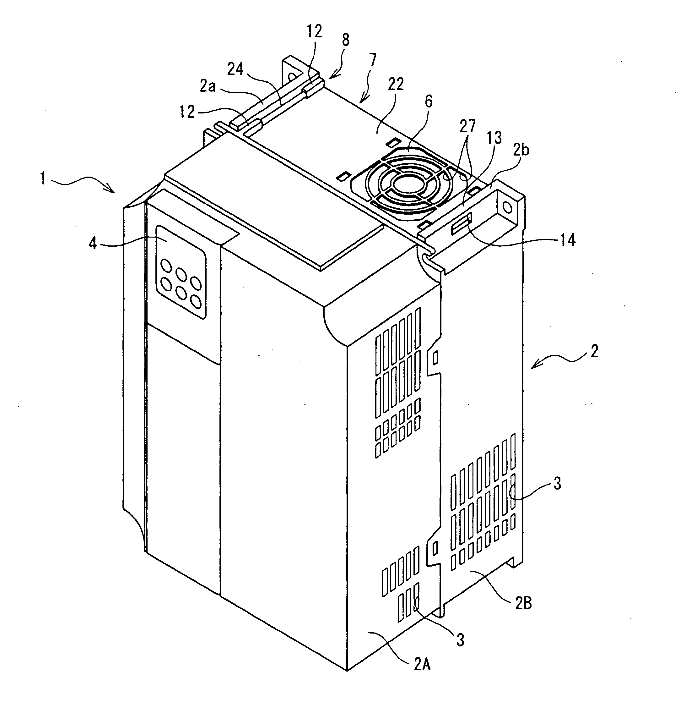
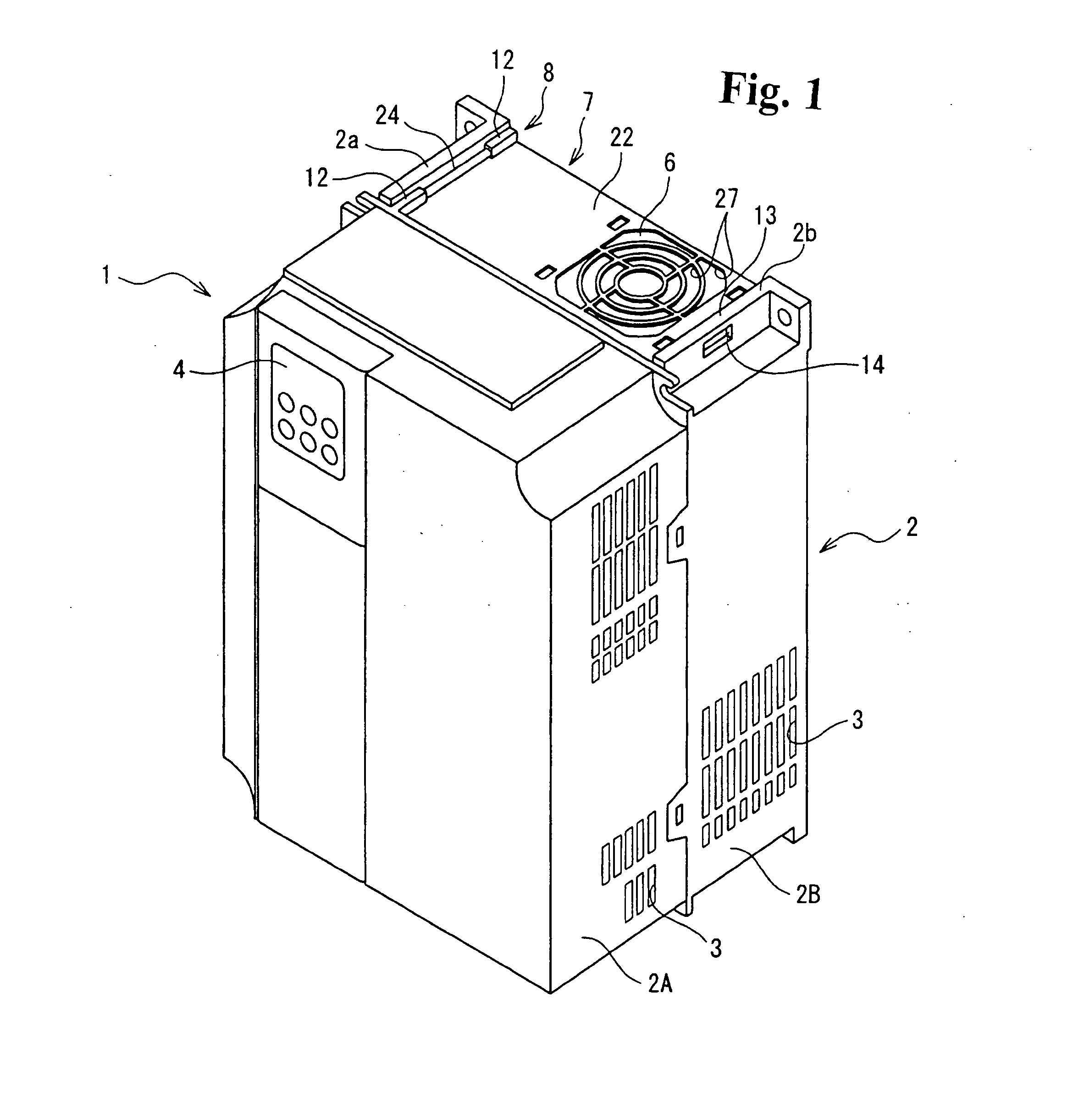
[0022]FIG. 1 is an external perspective view showing an inverter device acting as a power converting device. In this drawing, numeral 1 is the inverter device acting as the power converting device, and includes a main body 2 in which is housed a switching element, such as an IGBT, as a heat producing member. The main body 2 has a configuration wherein front and rear case half-bodies 2A and 2B are connected together, and air intake vents 3 are formed in both of the case half-bodies 2A ad 2B.

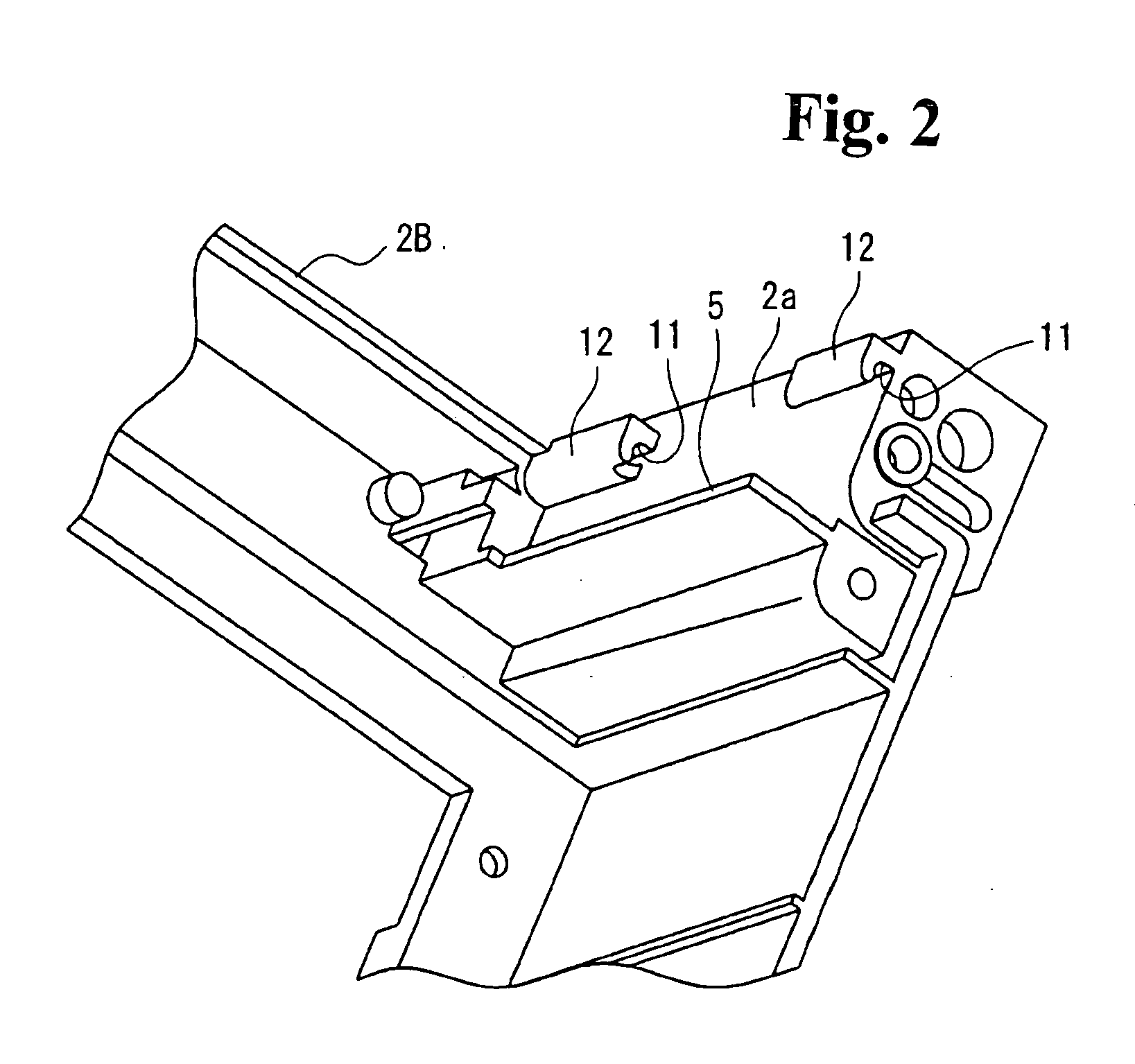
[0023]An operation display module 4, with which various kinds of operation, settings, and data are displayed, is provided in the front case half-body 2A. Also, a fan housing portion 5 is formed over the whole of the top surface, in an uppermost portion, of the rear case half-body 2B. A fan case 7, in which is mounted a cooling fan 6, is attachably and detachably disposed in the fan housing portion ...


PUM


Abstract

A power converting device includes a main body having a heat producing part housed therein, a fan case having a cooling fan therein for cooling the heat producing part provided in the main body, and a housing portion in the main body which houses the fan case. The fan case and the housing portion are interconnected so that the fan case is pivotally attached to and detached from the housing portion.

Description

BACKGROUND OF THE INVENTION AND RELATED ART STATEMENT[0001]The present invention relates to a power converting device which encloses a cooling fan in a main body housing of a heat producing device, and in particular, relates to a power converting device in which it is possible to easily replace the cooling fan.[0002]As this kind of power converting device, there is known an inverter with, for example, a heat producing device housed inside a main body, and a cooling fan for cooling. The fan includes a fan unit case which houses the cooling fan. A housing space is formed in an external side of an upper surface of the inverter device main body, and such that the fan unit case can be slid into and housed therein. A fan cover which fixes the fan unit case in place, is fixed to the fan unit case without screwing by a pawl, and in such a way that the fan unit case can be inserted and removed from the fan unit case housing space by sliding it backwards and forwards (for example, refer to JP...

Claims


Application Information

Patent Timeline
IPC IPC(8): F01D25/24
CPCH05K7/20918H02M7/003
Inventor HATOZAKI, YOSHIHISASHINTANI, TAKANORI
Owner FUJI ELECTRIC CO LTD
Why Eureka
Try Eureka