Fishing reel

Active Publication Date: 2015-04-02
SHIMANO INC
View PDF10 Cites 5 Cited by
  • Summary
  • Abstract
  • Description
  • Claims
  • Application Information

AI Technical Summary

Benefits of technology

[0021]In this configuration, the fixing agent, for example, the adhesive, can infiltrate from the first gap between the first region and the insertion hole to the third gap between the third region and the insertion hole. Thus, the third region that forms the third gap functions as a region for retaining the excess adhesive. Accordingly, it is possible to fill the adhesive in the first gap and the third gap, and the spool body and the spool shaft can be more reliably fixed.
[0022]According to the present invention, it is possible to provide a fishing reel capable of improving the positioning precision of the spool body in relation to th

Problems solved by technology

Therefore, there is a concern that the adhesive that is coated in the insertion region of the spool shaft will be pushed out from the gap.
Consequently, there is a concern that the adhesive will not be uniformly disposed in this gap.
Such a large gap may negatively affect the positioning precision of the spool body in relation to the spool shaft in the radial direction.
Therefore, when the insertion region of the spool shaft is inserted into the insertion hole of the spool body, t

Method used


Image

  • Fishing reel
  • Fishing reel
  • Fishing reel

Examples


Example

First Embodiment

1. Overall Configuration of the Reel

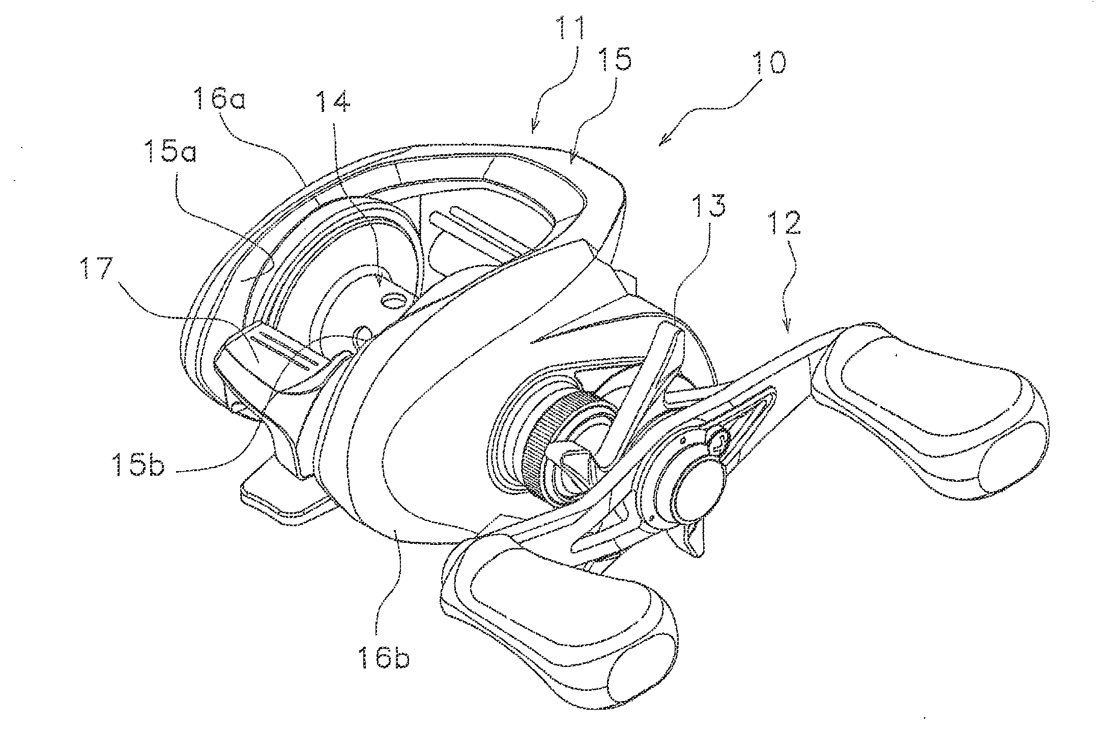
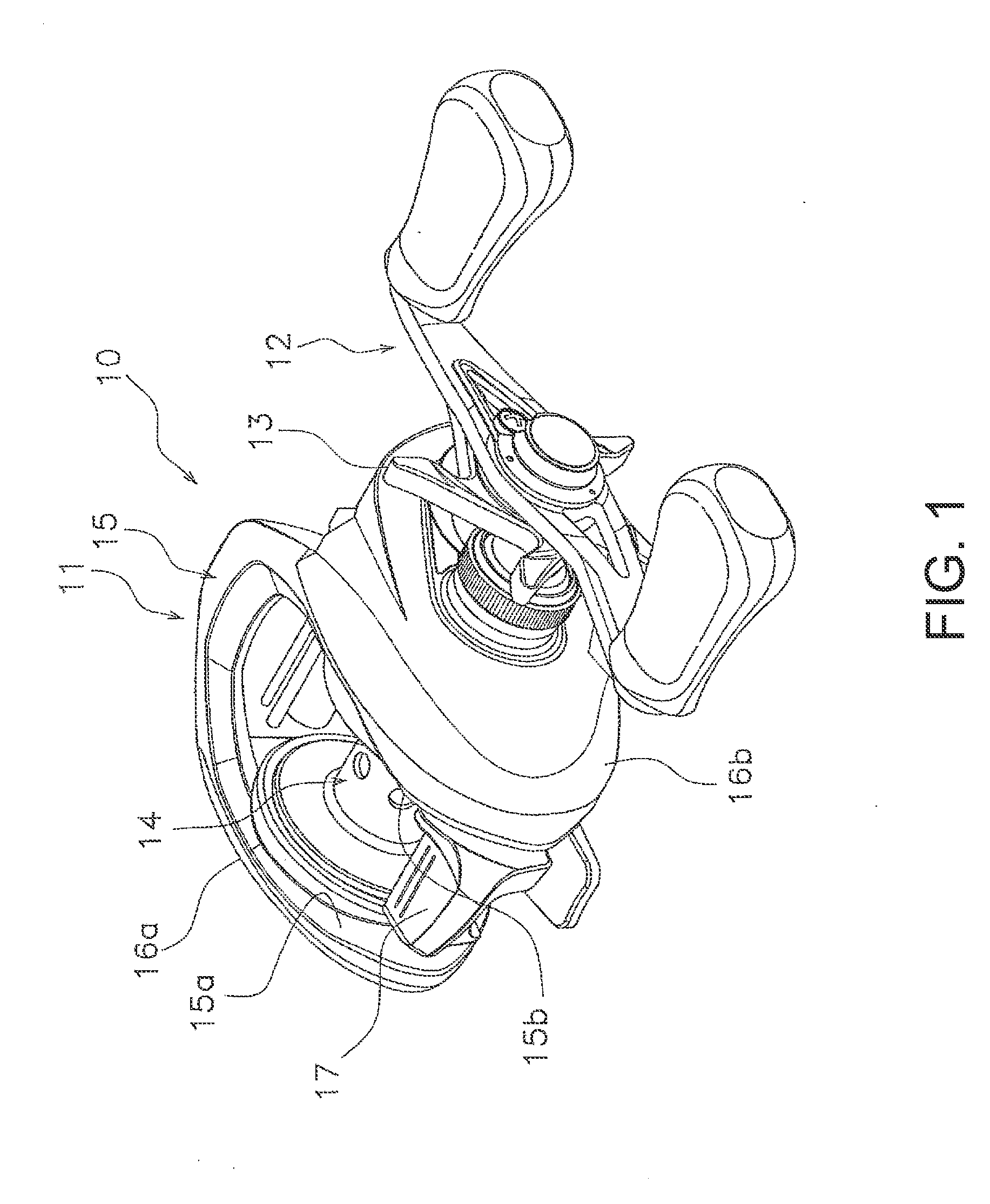
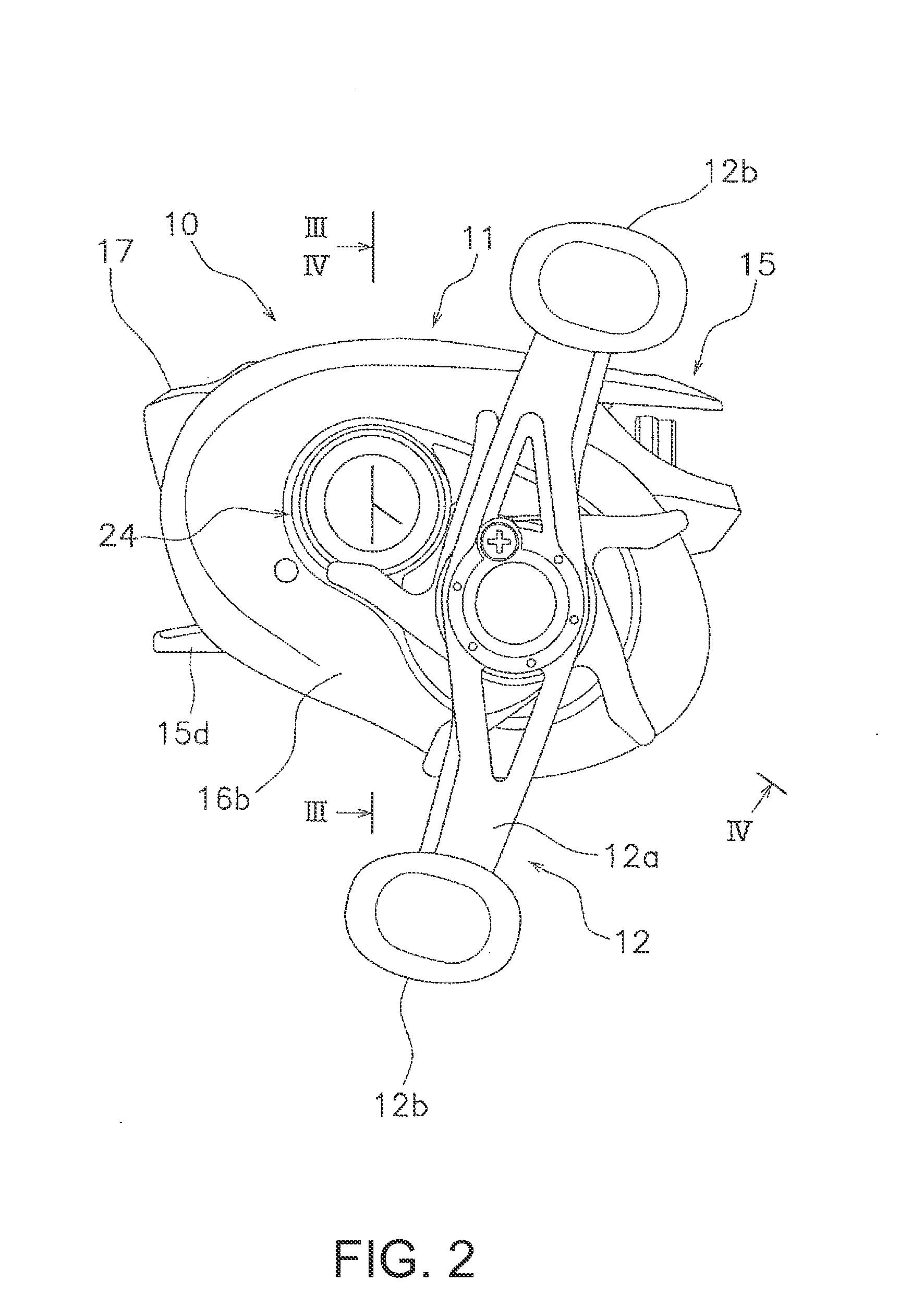
[0037]As illustrated in FIG. 1 to FIG. 4, the dual-bearing reel 10 according to an embodiment of the present invention is a dual-bearing reel for bait casting. This reel is equipped with a reel body 11, a handle 12 for rotating a spool unit 9 disposed at the side of the reel body 11, a star drag 13 for adjusting the drag disposed on the reel body 11 side of the handle 12, and the spool unit 9 comprised of a spool body 14 and a spool shaft 20.

[0038]The handle 12 has an arm part 12a and a handle 12b that is rotatably mounted on both ends of the arm part 12a. The arm part 12a is non-rotatably mounted to the extreme end of the drive shaft 30 and is fastened to the drive shaft 30 with a nut 28. The handle 12 is disposed on the second cover 16b side described below.

2. Configuration of the Reel Body

[0039]The reel body 11 is a member made from a light metal such as a magnesium alloy or the like. As illustrated in FIG. 1 to FIG. 4, the reel...

Example

Second Embodiment

[0083]In the second embodiment, the configuration of the spool shaft 20 varies from that of the first embodiment. The configurations other than that of the spool shaft 20 are the same as those in the first embodiment. Therefore, their description have been omitted here. Also, the same reference symbols are used for the configurations identical to those in the first embodiment. The configurations that lave been omitted here shall be based on the descriptions in the first embodiment.

1. Configuration of the Spool Shaft

[0084]As illustrated in FIG. 9, the spool shaft 20 has a shaft body part 115 and a protruding pin 116. The mounted part 120 of the shaft body part 115, for example, the large diameter part 20a has a pin mounting hole 120a disposed in the radial direction of the spool shaft 20. The pin mounting hole 120a is a hole with a bottom disposed in the radial direction of the spool shaft 20 in the mounted part 120. A protruding pin 116 is mounted in the pin mountin...

Example

Third Embodiment

[0087]In the third embodiment, the configuration of the spool unit 9 varies from that in the first embodiment. The configurations other than those of the spool unit 9 are the same as those in the first embodiment. Therefore, their descriptions have been omitted here. Also, the same reference symbols are used for the configurations identical to those in the first embodiment. The configurations that have been omitted here shall be based on the descriptions in the first embodiment.

1. Configuration of the Spool Unit

[0088]As illustrated in FIG. 10A to FIG. 10C, the spool unit 9 is primarily includes a spool body 14 and a spool shaft 20. The spool body 14 has a shell portion 14b, a flange portion 14a, and a shaft mounting portion 14d.

[0089]The shaft mounting portion 14d has a mounting part body 214a and a bent portion 214b. The mounting part body 214a is formed into a cylindrical shape. The bent portion 214b is the portion where one end portion of the mounting part body 2...


PUM


Abstract

A dual-bearing reel includes a reel body, a spool shaft, and a spool body. The spool shaft is rotatably mounted to the reel body. The spool body is non-rotatably mounted to the spool shaft. The spool body has an insertion hole. The spool shaft is inserted into the insertion hole. The spool shaft has an insertion region. The insertion region is inserted into the insertion hole and is disposed to oppose a surface of the insertion hole. The insertion region has a first region and a second region. A first gap is disposed between the first region and the insertion hole. A second gap that is smaller than the first gap is disposed between the second region and the insertion hole.

Description

CROSS-REFERENCE TO RELATED APPLICATIONS[0001]This application claims priority to Japanese Patent Application No. 2013-203881, filed on Sep. 30, 2013. The entire disclosure of Japanese Patent Application No. 2013-203881 is hereby incorporated herein by reference.BACKGROUND[0002]1. Field of Invention[0003]The present invention relates to a fishing reel.[0004]2. Background Information[0005]A fishing reel, for example, a dual-bearing reel can include a reel body, a spool shaft on which the reel body is rotatably mounted, and a spool body that is non-rotatably mounted to the spool shaft (refer to Japanese Patent Application Publication No. 2007-97474 and Japanese Unexamined Patent Application Publication No. H11-225633). The spool body has an insertion hole for the insertion of the spool shaft. The spool shaft has a region an insertion region) that opposes a surface of the insertion hole. Also, the spool shaft has the same diameter in the insertion region. A prescribed gap is formed betw...

Claims


Application Information

Patent Timeline
IPC IPC(8): A01K89/015
CPCA01K89/015
Inventor IKEBUKURO, SATOSHI
Owner SHIMANO INC
Why Eureka
Try Eureka