
Lug structure of drum

Active Publication Date: 2009-07-09
YAMAHA CORP
View PDF4 Cites 4 Cited by
  • Summary
  • Abstract
  • Description
  • Claims
  • Application Information

AI Technical Summary

Benefits of technology

[0012]The present invention has been conceived in light of such difficulties. An object of the invention is to provide a drum lug structure capable of enhancing the positional precision of a lug installed on a lug base with stability.
[0013]A further object of the invention is to provide a drum lug structure enabling easy installation and removal of a lug.
[0014]Still a further object of the invention is to provide a drum lug structure enabling easy adjustment of the drum tone.

Problems solved by technology

This gives rise to a difficulty in which, after installing the lug 50 on the lug base 52, the lug 50 readily becomes an inclined state in the direction of the arrows R.
As a result, when in a state of preparation to install the rim and similar, the lug 50 in FIG. 7 and the lug nut 63 in FIG. 8 move easily, and so must be held by hand, and for this and other reasons, there is the difficulty that working conditions are worsened.

Method used


Image

  • Lug structure of drum
  • Lug structure of drum
  • Lug structure of drum

Examples


Embodiment Construction

[0038]Below, preferred embodiments of the invention will be explained with reference to the drawings.

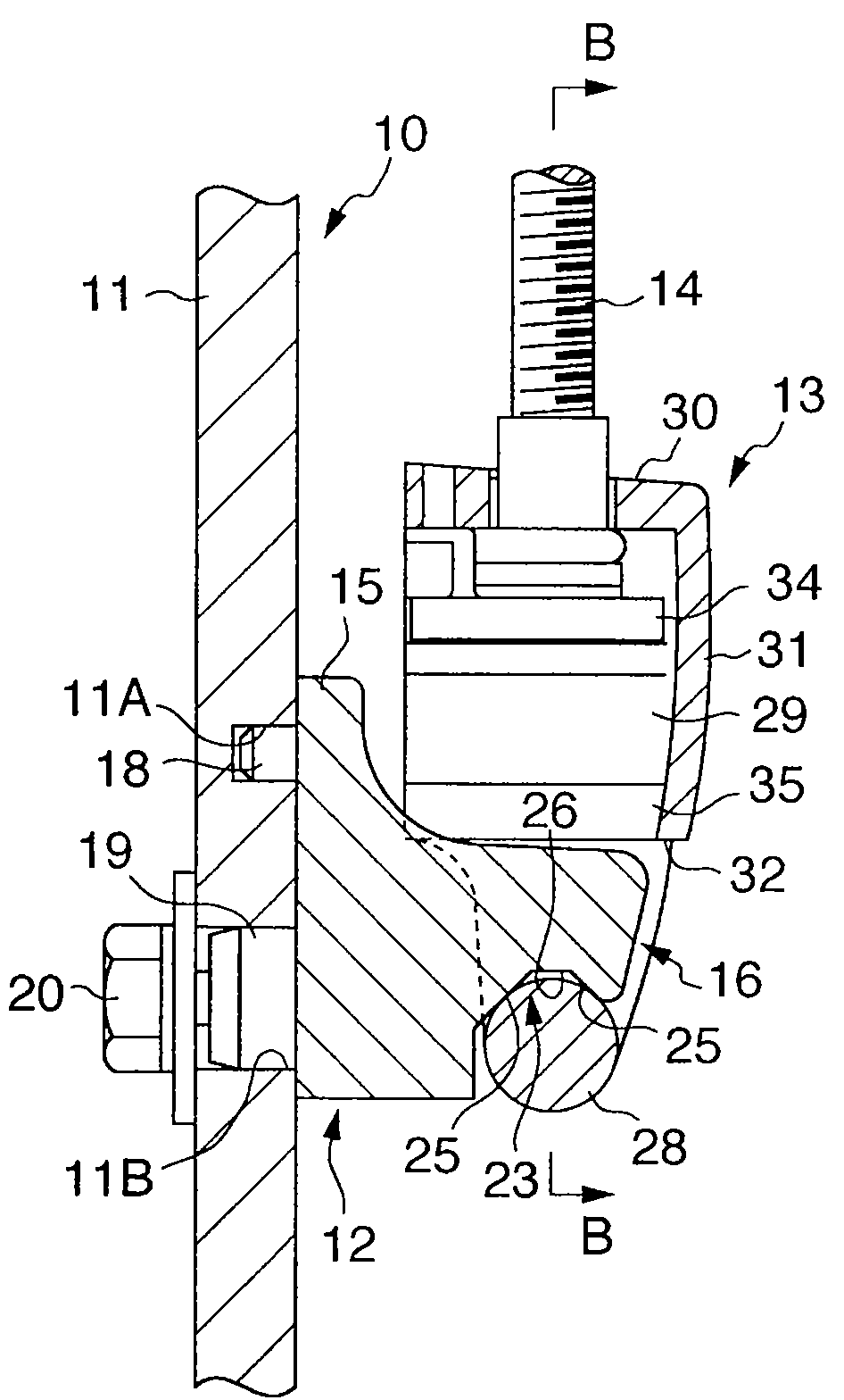
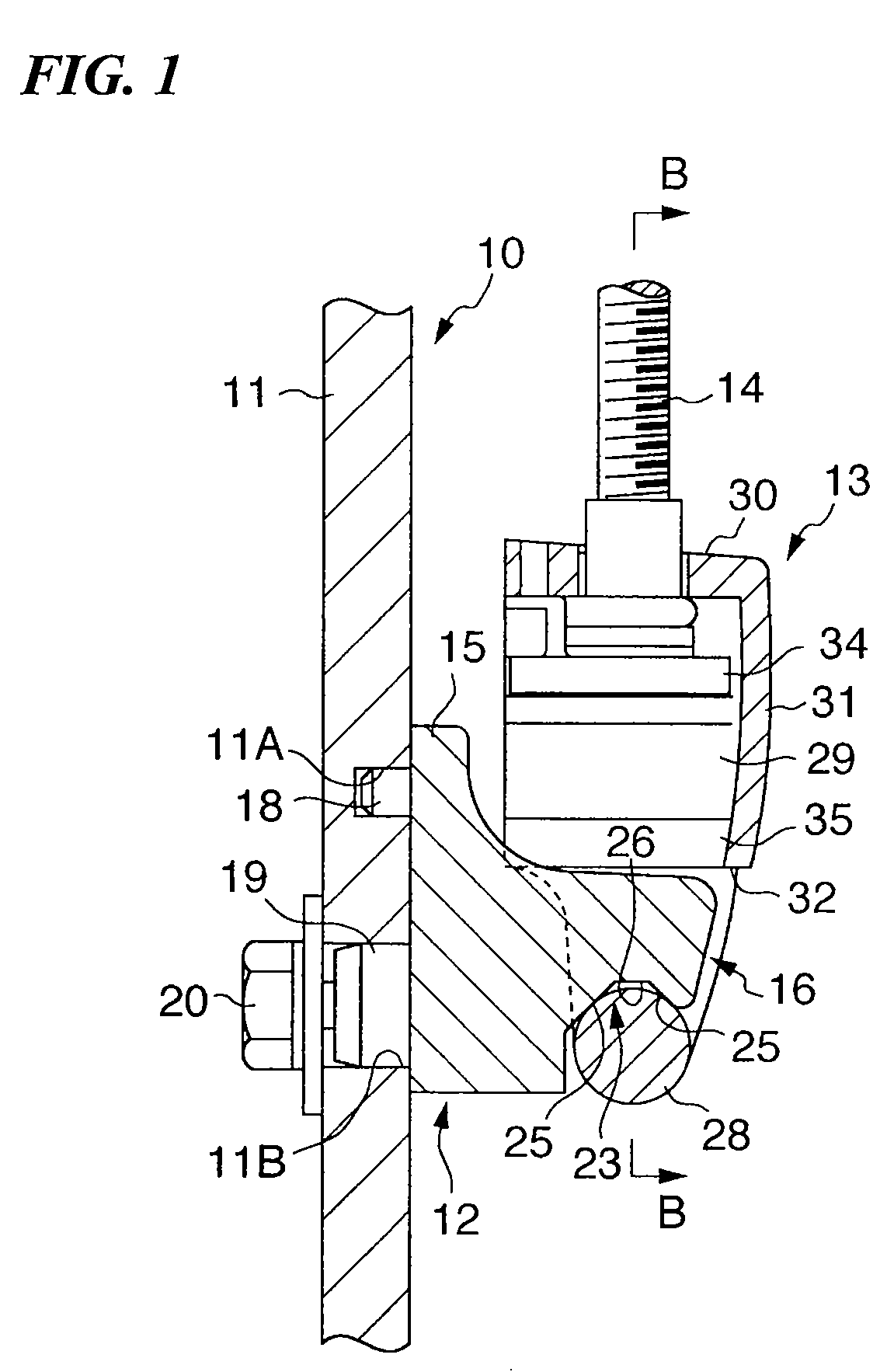
[0039]FIG. 1 is a side cross-sectional view showing a portion of a structure of a drum to which a lug structure according to an embodiment of the present invention is applied. A drum 10 show in FIG. 1 is a bass drum, snare drum, marching drum, or similar. The drum 10 includes a drum head (not shown) provided in a tensioned state on the upper portion in the figure of a drum shell 11, with a rim or similar (not shown) intervening. On the drum shell 11 is installed the lug base 12. A lug 13 is held by this lug base 12. The lug 13 holds the lower-end side in the figure of a tightening bolt 14, the upper portion of which is linked with the rim.

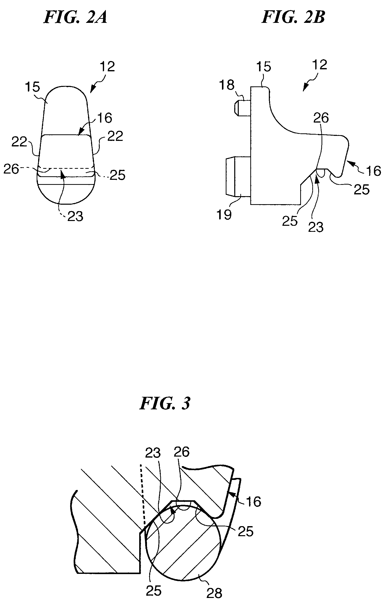
[0040]As shown in FIG. 1, FIG. 2A, and FIG. 2B, the lug base 12 includes an installation portion 15 along the outer-peripheral surface of the drum shell 11, and a protruding portion 16 which protrudes from the portion in the center in the vertical d...


PUM


Abstract

The lug structure of a drum for installing a drum head on a drum shell according to the present invention, includes: a lug base which is installed on the drum shell; a lug which is held by the lug base, and which supports one end of a tightening bolt; and a lug movement restraining portion which is provided between the lug base and the lug, and includes a shaft-shape portion provided on the lug, two planar portions are provided on the lug base, and the two planar portions extends substantially parallel to a shaft line of the shaft-shape portion and is contactable with the shaft-shape portion.

Description

BACKGROUND OF THE INVENTION[0001]1. Field of the Invention[0002]The present invention relates to a drum lug structure, and in particular relates to a drum lug structure capable of imparting a prescribed tension to the drum head.[0003]Priority is claimed on Japanese Patent Application No. 2008-001084, filed Jan. 8, 2008, the content of which is incorporated herein by reference.[0004]2. Description of the Related Art[0005]Drum lug structures of various drums such as shown for example in FIG. 7, FIG. 8A and FIG. 8B are known in which lugs are used in order to provide, in a tensioned state, the drum head over the drum shell, with a rim or similar intervening (see Japanese Patent Publication No. 3707485 [Japanese Unexamined Patent Application, First Publication No. 2004-151701]).[0006]In FIG. 7, the upper portion of a lug 50 holds a tightening bolt 51, and the lug 50 is installed on the drum shell 53 via a pin-shape lug base 52. In the lug base 52 is formed a V-shape engagement groove 52...

Claims


Application Information

Patent Timeline
IPC IPC(8): G10D13/02
CPCG10D13/023G10D13/16G10D13/02
Inventor YAMAMOTO, TAKETOSHI
Owner YAMAHA CORP
Learn More