Rapidly assembleable and disassembleable display rack

a display rack and rapid technology, applied in the field of display racks, can solve the problems of compromising the integrity of the display rack, difficult to handle during set up and take down, and large racks, and achieve the effect of convenient and compact placement within a container, easy assembly and disassembly

Inactive Publication Date: 2007-08-02
PREST J DAVID
View PDF19 Cites 18 Cited by
  • Summary
  • Abstract
  • Description
  • Claims
  • Application Information

AI Technical Summary

Benefits of technology

[0007] The present invention is directed to a lightweight, easily assembleable and disassembleable display rack having particular utility at temporary locations, such as trade shows and the like. The display rack is assembleable from a plurality of essentially planar elements that are readily and compactly placed within a container for storage and/or transport purposes. During assembly, the various elements are readily either mechanically locked into place or secured in place by nylon ties or the like. During disassembly, mechanical unlocking is easily done and the nylon ties may be snipped to

Problems solved by technology

These display racks tend to be large, cumbersome and heavy, which features render them difficult to handle during set up and take down.
Numerous parts, such as nuts and bolts, are time consuming to attach and detach from the corresponding elements; moreover, they are easi

Method used


Image

  • Rapidly assembleable and disassembleable display rack
  • Rapidly assembleable and disassembleable display rack
  • Rapidly assembleable and disassembleable display rack

Examples


Embodiment Construction

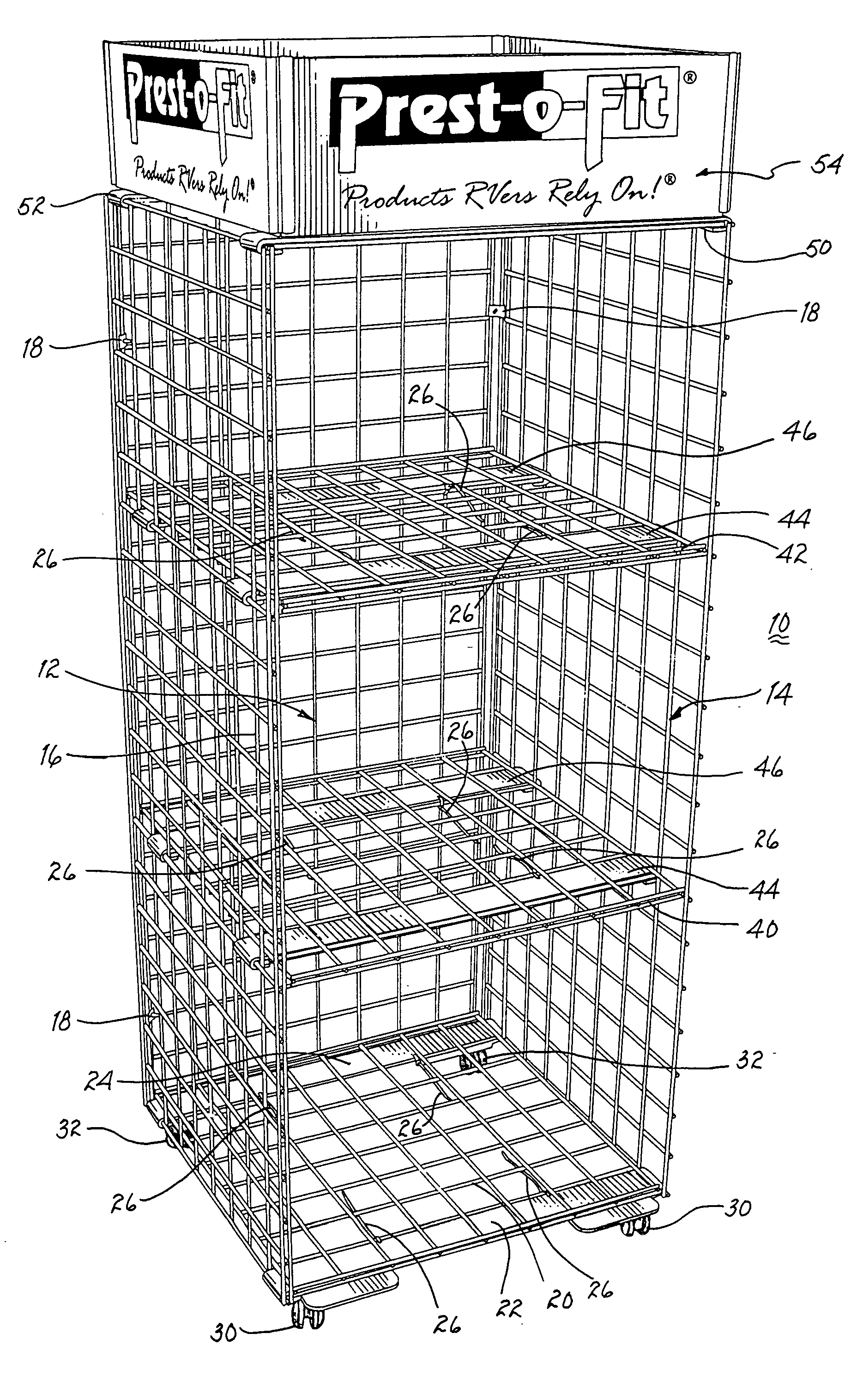
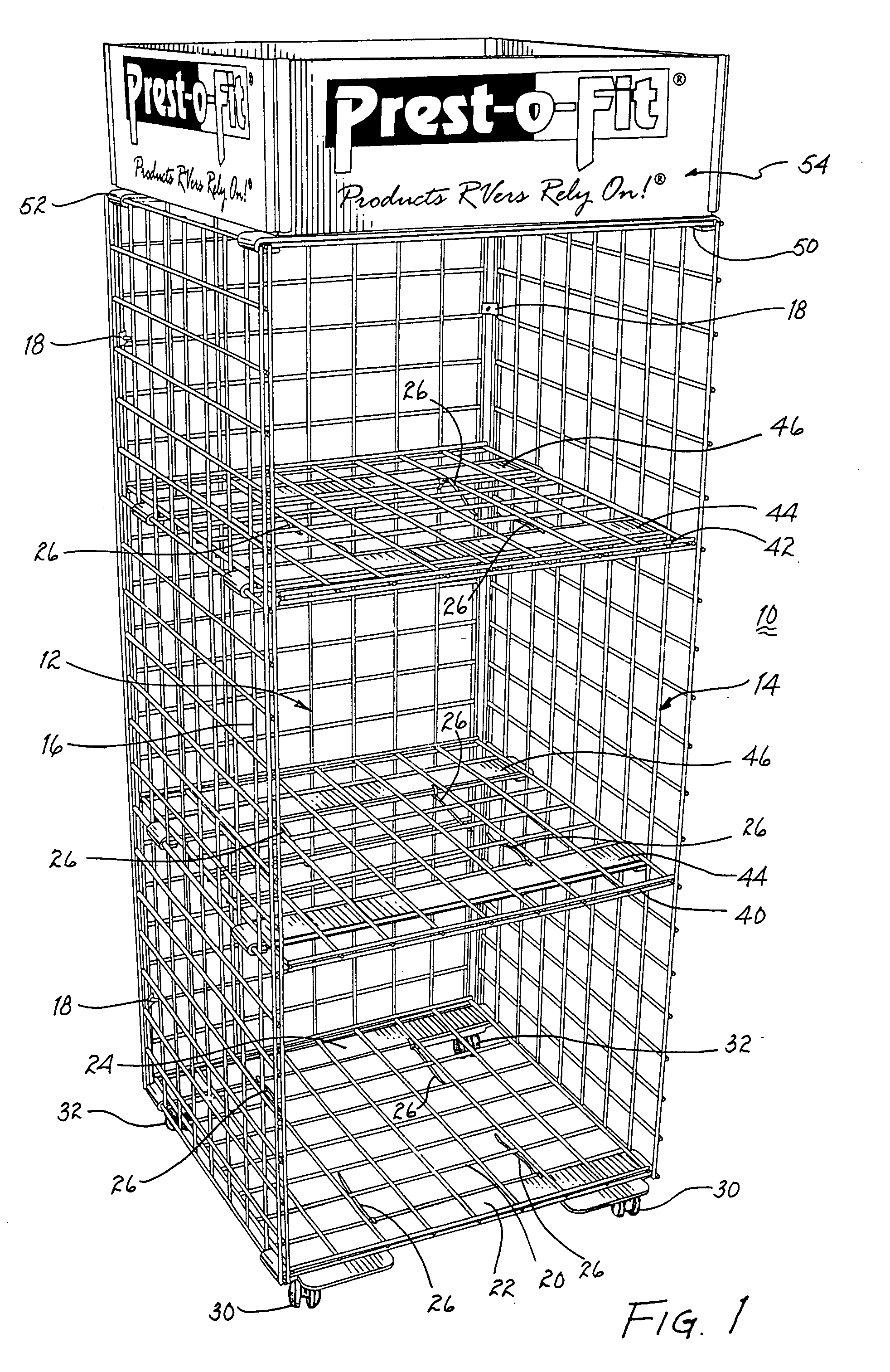
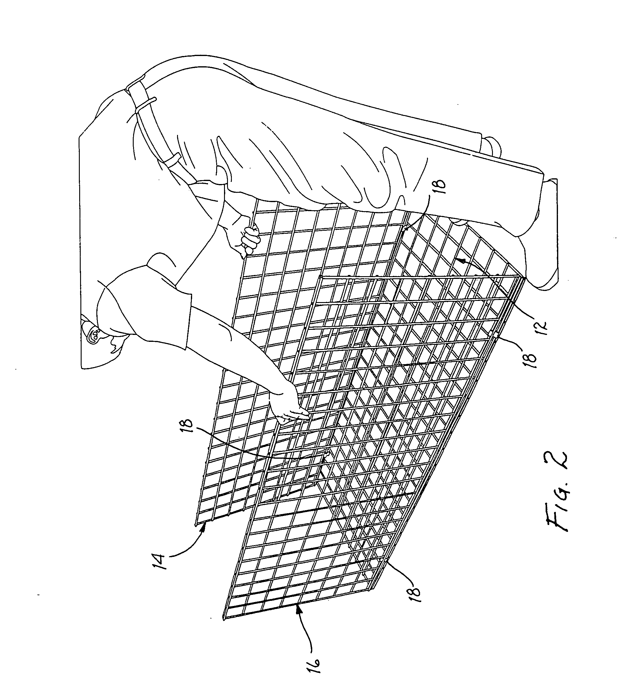
[0036] Referring to FIG. 1, there is illustrated a display rack 10 embodying the principles of the present invention. The display rack includes a rear grid wall 12 and a pair of side grid walls 14, 16 are hingedly attached to the back grid walls by commercially available hinges 18 conventionally used for this purpose. A bottom shelf 20 of grid wall material is supported upon strap units 22, 24 that engage side grid walls 14, 16. The shelf may be attached to the strap units by nylon ties 26. Strap unit 22 may support a pair of wheel assemblies 30 and strap unit 24 supports a pair of wheel assemblies 32. Thereby, display rack 10 may be easily moved from one location to another.

[0037] Further shelves of grid wall material, such as shelves 40, 42 are supported by strap units 44, 46 at vertical locations commensurate with the items to be placed thereon. Like bottom shelf 20, shelves 40, 42 are secured to strap units 44, 46 by nylon ties 26. A pair of strap units 50, 52 secure the upper ...


PUM


Abstract

Opposed walls of three hingedly attached grid walls are secured to one another by a first strap having folded back ends for partially encircling a segment of a wire element of each opposed grid wall. A second strap is placed adjacent the first strap with the ends of the second strap bearing against the partially encircled wire elements to retain the wire elements within the respective folded back ends. Nylon ties or bolts may be used to secure the first and second straps to one another. Two or more pairs of first and second straps support a grid wall serving as a shelf and the shelf may be secured to the straps by pairs of nylon ties. To provide mobility to the display rack, fixed or pivotable wheels are supported by the lowermost pairs of first and second straps and may be secured thereto by nylon ties or by nut and bolt combinations. A billboard unit having four panels is formed by two three-segmented panels placed orthogonally upon one another to permit upward bending of the pairs of outer panels. A slide having two orthogonal channels interconnect with and retain adjacent edges of the upwardly bent panels. The billboard unit may be secured in place at the top of the display rack with nylon ties. To disassemble the display rack, each nylon tie is snipped to permit removal of the elements of the display rack and the first and second straps a re disengaged from one another, whereby the display rack is quickly dismantled for storage and/or transport.

Description

BACKGROUND OF THE INVENTION [0001] 1. Field of the Invention [0002] The present invention relates to display racks, and, more particularly, to display racks which are light in weight and quickly assembleable and disassembleable. [0003] 2. Description of Related Prior Art [0004] At trade shows and the like, manufacturers and distributors of various products or services usually display their wares on display racks of various types. These display racks tend to be large, cumbersome and heavy, which features render them difficult to handle during set up and take down. Of the display racks presently available that are disassembleable for storage and / or transport, tools, such as screwdrivers, pliers, wrenches, etc. are often required to be used. Numerous parts, such as nuts and bolts, are time consuming to attach and detach from the corresponding elements; moreover, they are easily lost which may compromise the integrity of the display rack. [0005] The weight and size of presently used dis...

Claims


Application Information

Patent Timeline
IPC IPC(8): A47B43/00
CPCA47F5/137
Inventor PREST, J. DAVID
Owner PREST J DAVID
Why Eureka
Try Eureka