Anti-theft nut and bolt assembly

a nut and bolt technology, applied in the direction of threaded fasteners, screws, fastening means, etc., can solve the problems of inconvenience for the owner or operator of the property in replacing the nut and bolt, damage to the retained members, and personnel danger, so as to improve the difficulty of unwanted removal

Inactive Publication Date: 2005-02-03
RIOUX ANDRE
View PDF0 Cites 8 Cited by
  • Summary
  • Abstract
  • Description
  • Claims
  • Application Information

AI Technical Summary

Benefits of technology

[0008] It is an object of the present invention to provide an anti-theft nut and bolt assembly having enhanced difficulty for unwanted removal of the nut and bolt therefrom.

Problems solved by technology

There are instances where the unwanted dismantling of a tightened nut and bolt assembly, i.e. by accident or the identical stealing of the nut and bolt can result in damage to the retained members, danger to personnel, and expense and inconvenience to the owner or operator of the property in replacing the nut and bolt.
One such example of the dangerous, unwanted stealing of tightened nuts and bolts occurs by their removal from free-standing tower structures, such as electricity pylons and communication towers, which cross both heavily inhabited and lightly inhabited geographic regions of a country.
However, in very many situations transporting the welding equipment to the site of the tower, for example, in the bush, jungle or mountainous regions; or welding the structural spars struts, girders and the like above ground is difficult and labour intensive, in requiring an extra, generally unionized, person, namely, a welder.
Further, the welding process destroys the localized galvanized surface.
Yet further, the weld spots can generally be easily ground off.

Method used


Image

  • Anti-theft nut and bolt assembly
  • Anti-theft nut and bolt assembly
  • Anti-theft nut and bolt assembly

Examples


Embodiment Construction

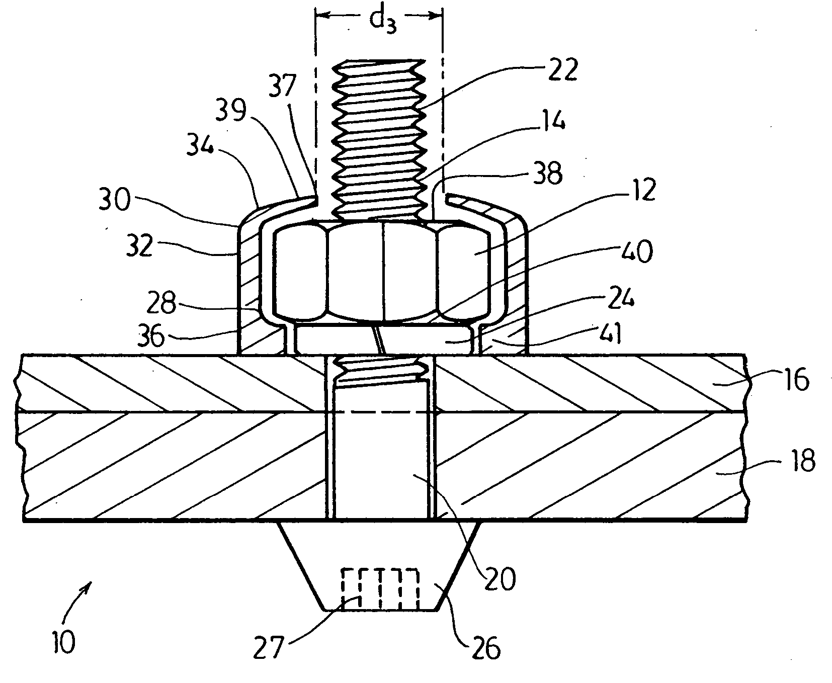
[0046] With reference to FIG. 1, this shows generally as 10, well-known heavy duty nut and bolt components, stainless steel threaded hexagonal nut 12 tightened on a stainless steel bolt 14 to retain two steel plates 16, 18 of a tower or pylon support (not shown). Nut 12 has an outer diameter d1.

[0047] Bolt 14 has a smooth body portion 20 and a complementary-threaded portion 22, upon which is tightened nut 12 and a lock washer 24 held on bolt portion 22 between nut 12 and plate 16. Bolt 14 has a partial conical head 26 having a pentagonal recess adapted 27 to receive a heavy-duty pentagonal key (not shown).

[0048] Washer 24 has an outer diameter d2 smaller than nut outer diameter d1, so as to provide a recess 28 with nut 12 and plate 16.

[0049] Surrounding nut 12 is a cylindrical steel casing 30 having a body 32 between an outer terminal portion 34 and an inner terminal portion 36 distant of portion 34 in abutment with plate 16.

[0050] Portion 34 defines a cylindrical aperture 37 of...


PUM


Abstract

A locked nut and bolt assembly for bolting a plurality of members one to another in tight abutment, the assembly having: a bolt having a head and a threaded body portion; a complementarily-threaded nut having a nut outside diameter received in locked engagement on the bolt; the plurality of members retained on the bolt between the head and the nut; a casing having—a first terminal portion defining an inwardly protruding retained portion defining a first aperture embracing the bolt body portion and the retained portion in abutment with and retained by the tightened nut; a second terminal portion defining an inwardly protruding covering portion defining a second aperture embracing the bolt body portion and the covering portion in covering close proximity to the nut as to prevent access to the nut by nut engaging and turning means to effect loosening thereof; and a body between the first and the second terminal portions and surrounding the nut in close proximity thereto as to define therebetween a receiving recess for the nut engaging and turning means. The assembly constitutes an anti-theft nut and bolt locking device having enhanced difficulty for unwanted removal of the nut and bolt.

Description

FIELD OF THE INVENTION [0001] This invention relates to a tightened nut and bolt assembly used to retain a plurality of members together in such a manner as to reduce the likelihood of unwanted removal by theft or accident and reuse of the nut and bolt from the assembly. It also relates to a kit of parts combination for use in said assembly; and to a method of forming said assembly. BACKGROUND TO THE INVENTION [0002] Threaded nuts and bolts of various sizes have been extensively used in a vast ubiquitous array of industries, utilities and situations for retaining a plurality of members, articles and the like, together. [0003] There are instances where the unwanted dismantling of a tightened nut and bolt assembly, i.e. by accident or the identical stealing of the nut and bolt can result in damage to the retained members, danger to personnel, and expense and inconvenience to the owner or operator of the property in replacing the nut and bolt. [0004] One such example of the dangerous, ...

Claims


Application Information

Patent Timeline
Patent Type & Authority Applications(United States)
IPC IPC(8): F16B41/00
CPCF16B41/005
Inventor RIOUX, ANDRE
Owner RIOUX ANDRE
Why Eureka
Try Eureka