
Pipe clamp with improved fastener

A technology for fasteners and pipe collars, which is applied in the direction of threaded fasteners, fasteners, connecting components, etc., and can solve problems such as uncertain joint strength and inconsistent nut torque

Active Publication Date: 2008-01-30
NORMA US HOLDING LLC
View PDF3 Cites 7 Cited by
  • Summary
  • Abstract
  • Description
  • Claims
  • Application Information

AI Technical Summary

Problems solved by technology

In the event of this interference, the screw-in torque applied to the nut 252 begins to vary, resulting in inconsistent nut torque, creating unpredictable clamping loads
Unpredictable clamp loads will result in uncertain joint strength

Method used


Image

  • Pipe clamp with improved fastener
  • Pipe clamp with improved fastener
  • Pipe clamp with improved fastener

Examples


Embodiment Construction

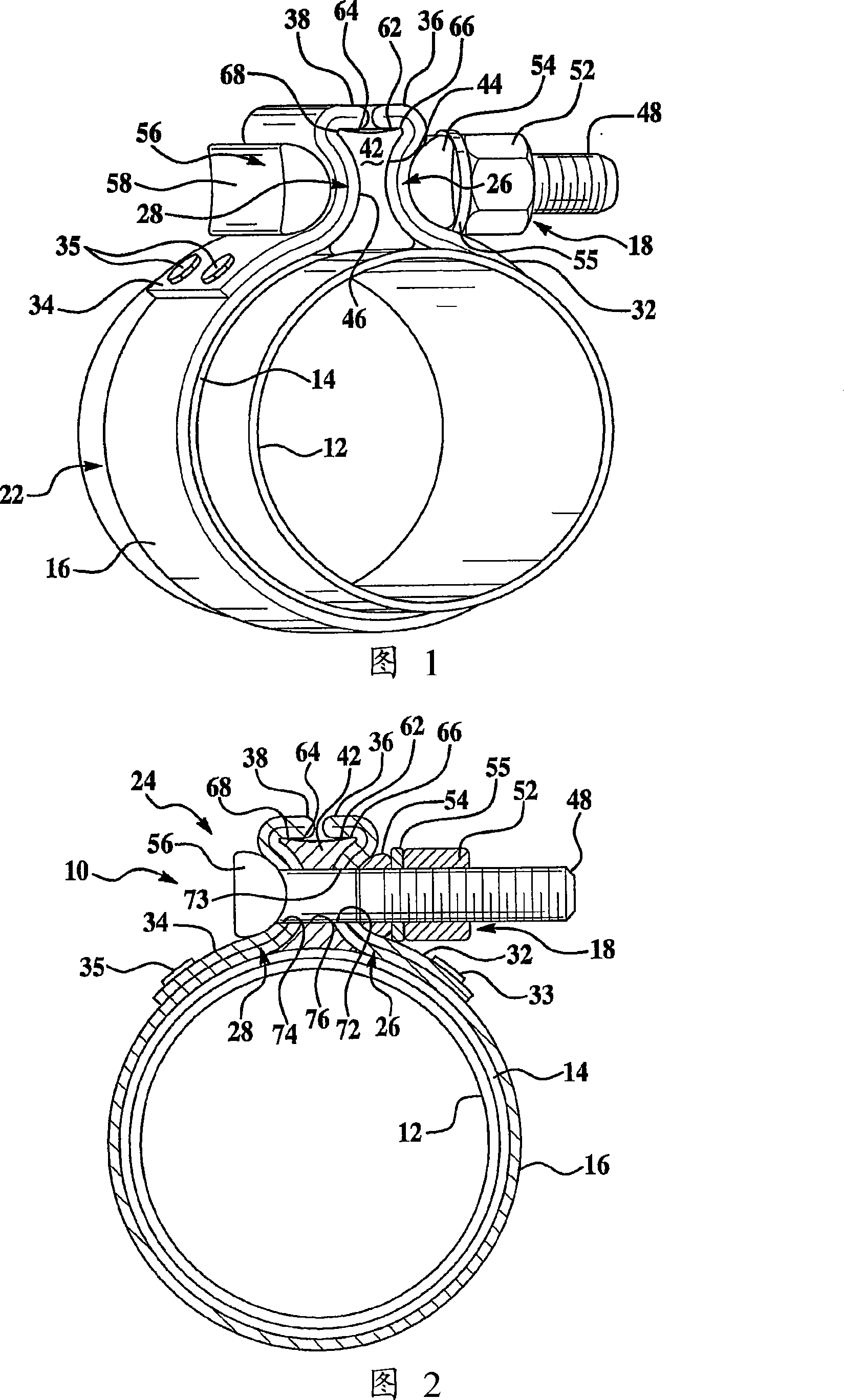
[0024] Two exemplary embodiments of a pipe clamp according to the invention, which are particularly suitable for joining together pipe ends in an automobile exhaust system to form a pipe joint, will be described below with reference to the accompanying drawings. In exhaust system applications, the pipe collar is preferably made of steel. In an exemplary embodiment, the present invention is implemented as a ferrule with a single bolt, the tightening member of which is disclosed in US Patent No. 4,629,226 to Cassel et al. The present invention can also be implemented as a tightening member with two bolts as disclosed in US Patent No. 4,813,270 to Cassel or US Patent No. 6,758,501 to Amedure et al. In the following description, it will be seen that the invention is useful in many different applications, and can be practiced in other embodiments. For example, the present invention is applicable not only to pipe collars for telescoping overlapping pipes, but also to pipe couplings...


PUM


Abstract

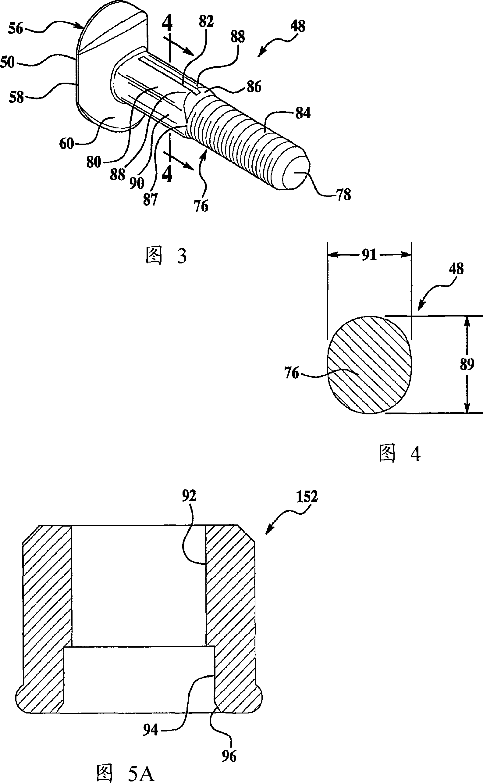
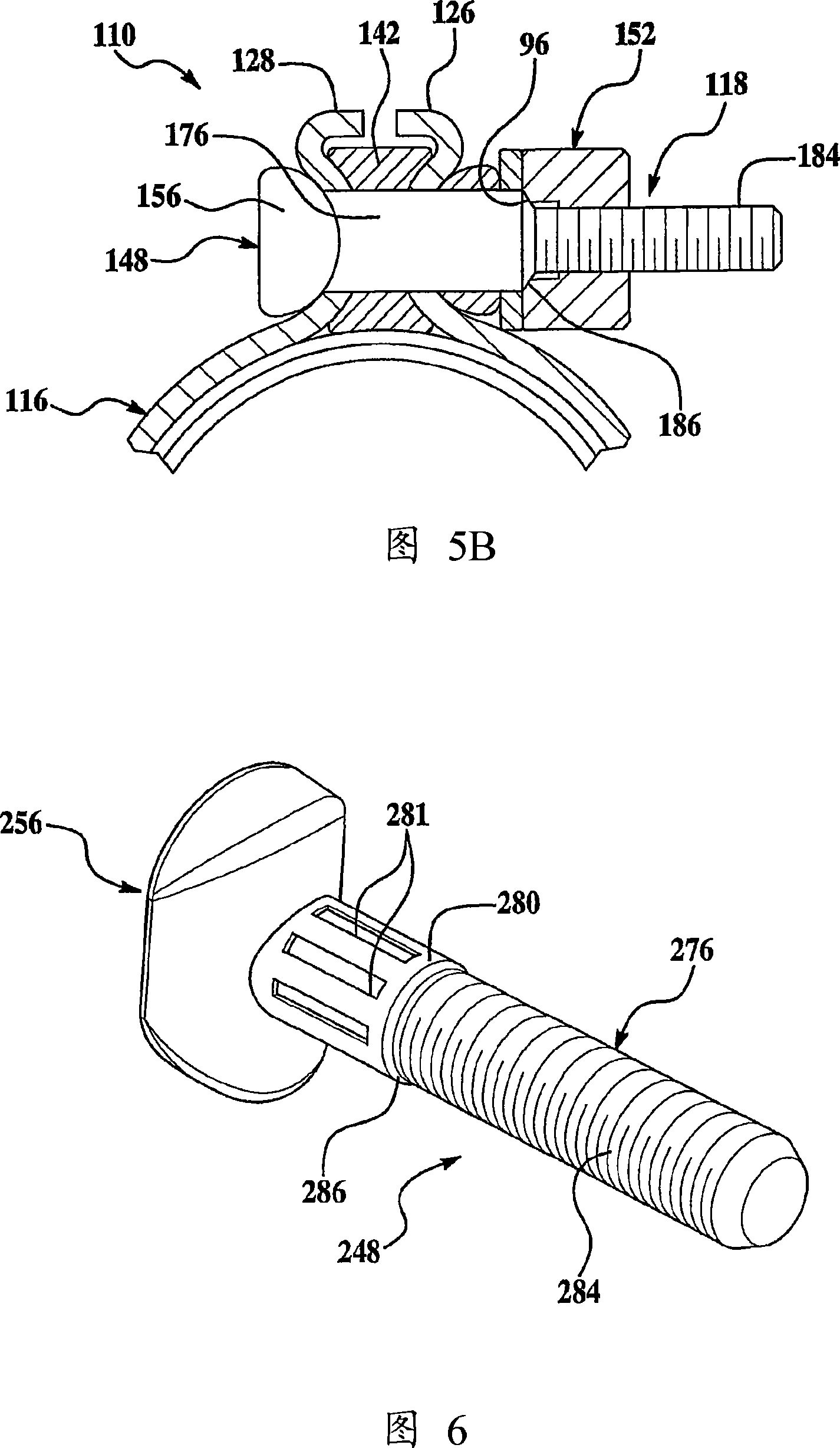
A pipe clamp with hoop, nut, and bolt fasteners. The hoop includes radially extending opposing flanges, each flange having an opening for receiving a bolt. The bolt has a shank that includes a neck, a threaded body for receiving the nut, and a tapered transition from the neck to the threaded body. In one embodiment, the tapered transition extends only partially around the stem, allowing a portion of the neck to have a common surface with the threaded body. During tightening, the radially inwardly facing surface of the opening in the flange can engage the threaded body and slide along the threaded body through the universal surface and onto the neck without being blocked and ridden by the tapered transition. On the tapered transition. In another embodiment, the nut has an angled shoulder that engages the tapered transition when the nut is tightened on the bolt to the desired axial position.

Description

technical field [0001] The present invention generally relates to pipe clamps, such as band clamps, pipe couplers, and the like. Background technique [0002] Couplings are commonly used to join pipes, hoses, and other tubular components together, such as exhaust pipes in automotive exhaust systems. This connection is typically made at an expansion lap joint of the two tubular members or at an end-to-end butt joint. To be usable, the connection between the tubular parts should be suitably fluid tight so as to prevent leakage. The connection should also have a high degree of mechanical strength and be easily detachable. [0003] Conventional ferrules include ferrules defined by a cylindrical portion to enclose a tubular member. The cylinder terminates in opposing, radially extending attachment flanges which are loosened and tightened about the tubular member by fasteners extending transversely through the flanges. When the fastener is tightened, the opposing flanges are c...

Claims


Application Information

Patent Timeline
Patent Type & Authority Applications(China)
IPC IPC(8): F16L33/04
CPCF16L33/04F16B35/048F16L21/065F01N13/1805F01N13/1855Y10T24/1441Y10T24/1451Y10T24/1455F16L33/00
Inventor 布赖恩·T·伊格纳茨卡迈克尔·E·艾默杜尔
Owner NORMA US HOLDING LLC
Learn More