Ultrasonic wave generating device
a technology of ultrasonic waves and generating devices, which is applied in the direction of mechanical vibration separation, instruments, bumpers, etc., can solve the problems of reducing the efficiency of generating ultrasonic waves, unable to send ultrasonic waves, and water drops or dust may adhere to the surface of the device, etc., and achieves efficient sending
- Summary
- Abstract
- Description
- Claims
- Application Information
AI Technical Summary
Benefits of technology
Problems solved by technology
Method used
Image

Examples
first embodiment
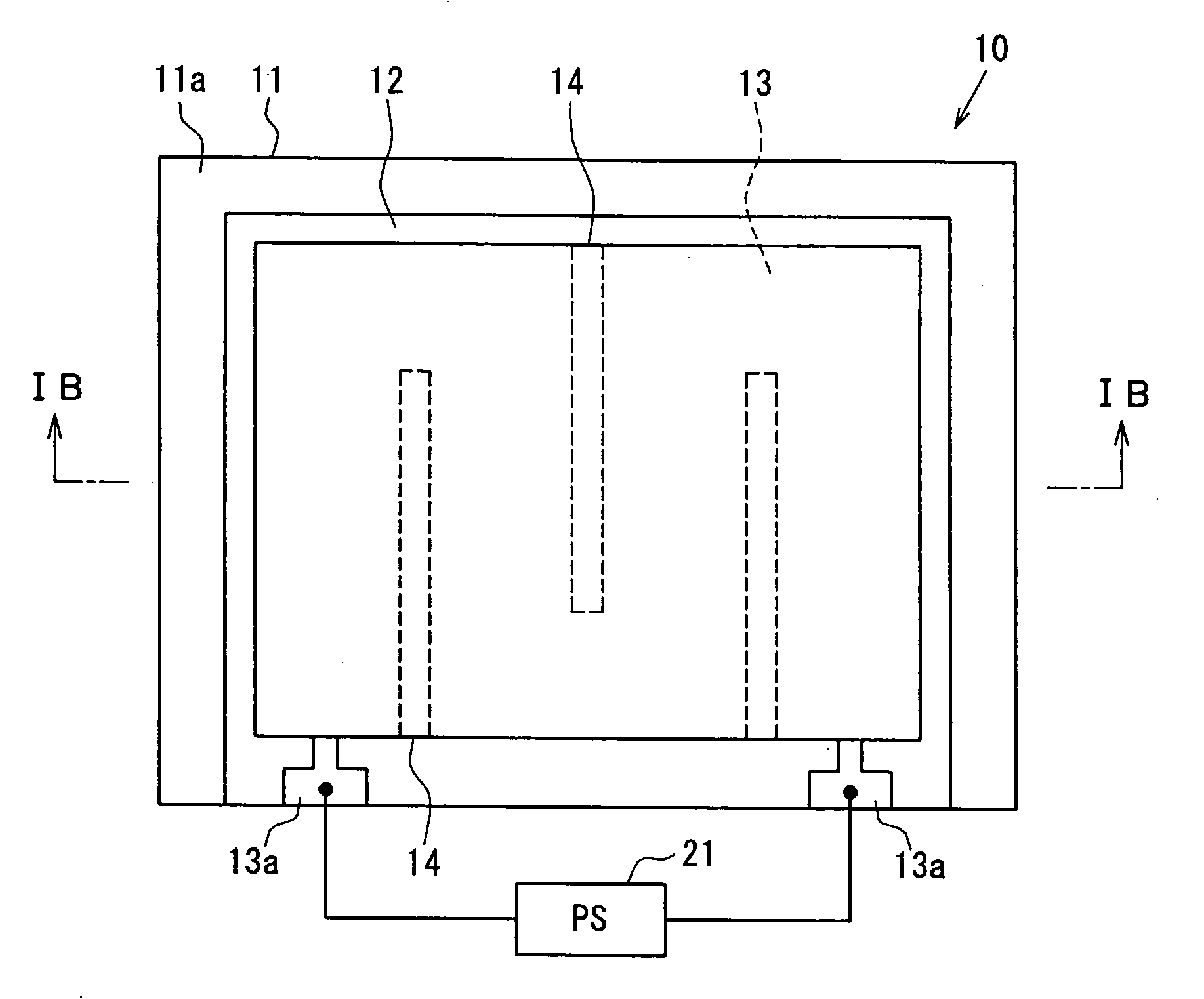
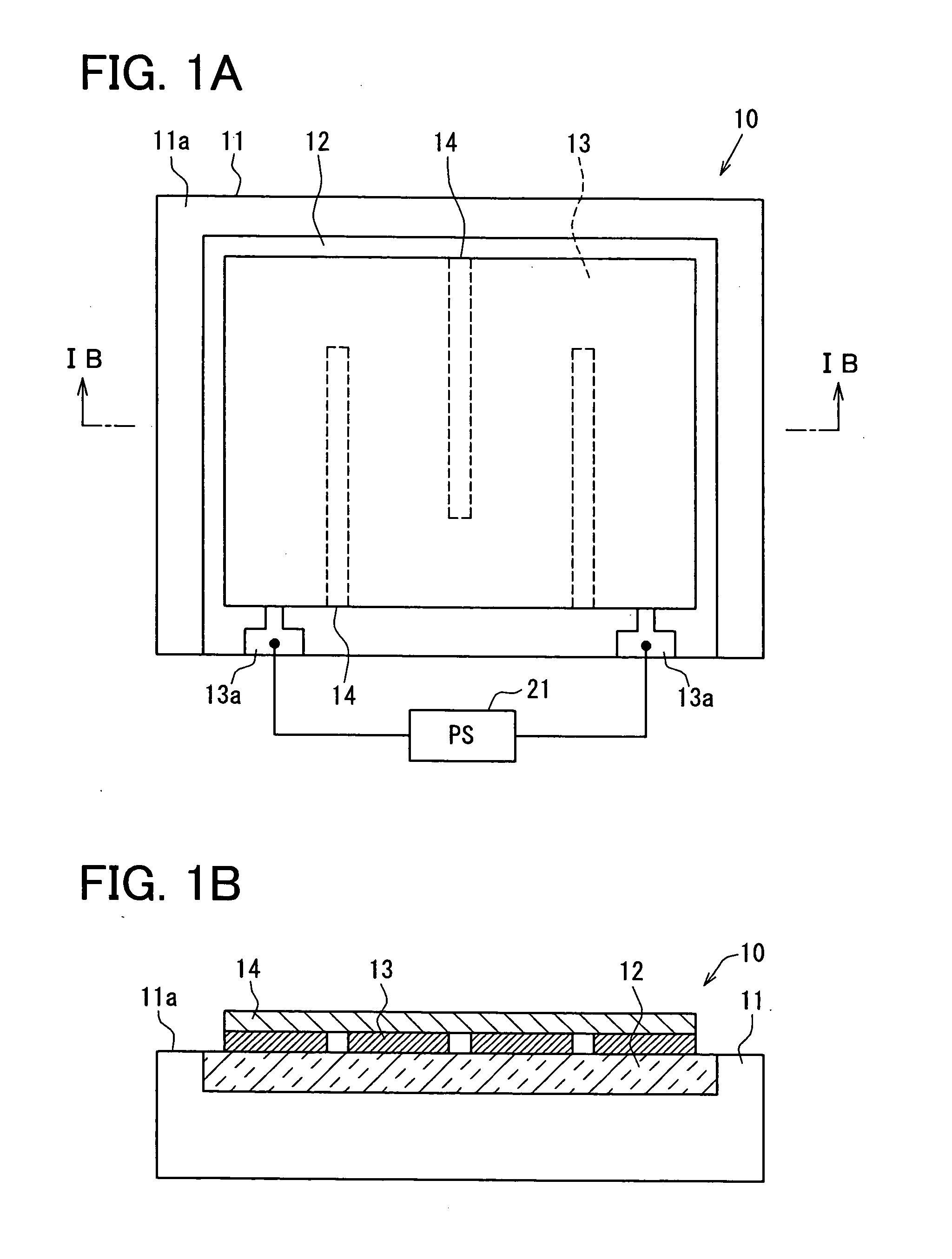
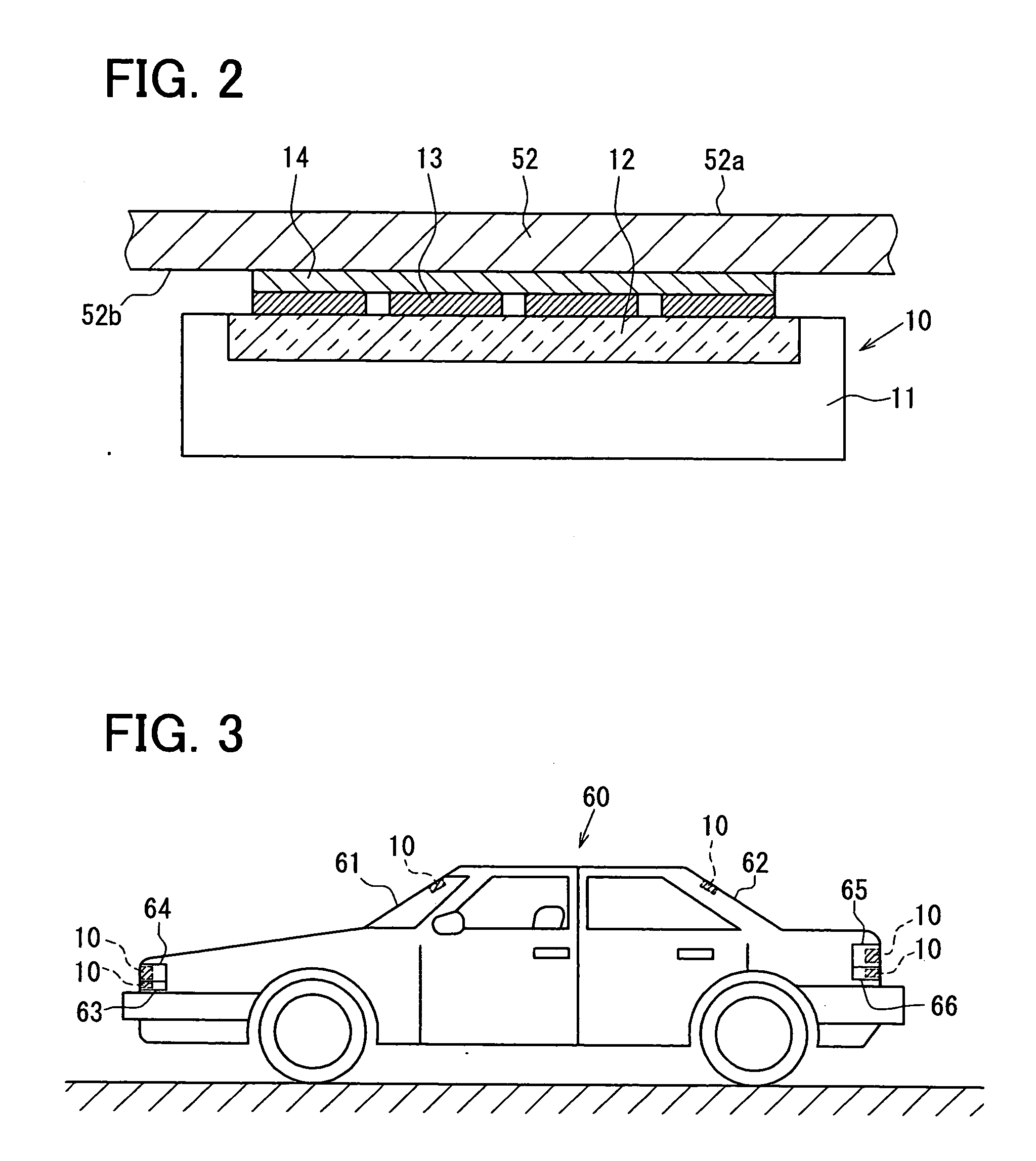
[0023]An ultrasonic wave generating device 10 is mounted to an automobile, and used in an obstacle detecting sensor in a first embodiment. As shown in FIGS. 1A and 1B, the device 10 is provided with a quadrangular substrate 11 made of silicon. A quadrangular heat insulation layer 12 made of porous silicon is formed in the substrate 11, and forms a part of a substrate face 11a of the substrate 11. The layer 12 is formed by electrochemically etching the substrate 11 from the substrate face 11a.
[0024]A heating portion 13 is formed on the layer 12 by layering a membrane made of tungsten. As shown in FIG. 1A, the heating portion 13 is formed into a zigzag on a quadrangular area of the layer 12 by a membrane process such as plating or sputtering. The heating portion 13 has electrode pads 13a protruded from an end of the heating portion 13, and the pads 13a are electrically connected to a power source (PS) 21 for driving and operating the heating portion 13. An oscillator 14 is formed on ...
second embodiment
[0035]As shown in FIG. 4, an ultrasonic wave generating device 30 in a second embodiment further includes a weight 15 on an oscillator 14. The weight 15 protects the oscillator 14 and amplifies amplitude of the oscillator 14. The weight 15 is made of a stainless board, and covers an oscillating face of the oscillator 14. A heating portion 13 is driven by electricity from the power source 21 (see FIG. 1A), and a period of the electricity varies in accordance with a period of an ultrasonic wave. Then, the oscillator 14 oscillates, and the weight 15 is displaced in accordance with a frequency of the oscillation. Thereby, a surface of the weight 15 oscillates so as to generate ultrasonic waves. At this time, amplitude of the oscillator 14 is increased compared with a case in which the weight 15 is not disposed on the oscillator 14, because the weight 15 pulls the oscillator 14, and promotes a displacement of the oscillator 14 due to an increased inertia of the oscillation. Thus, efficie...
third embodiment
[0041]As shown in FIG. 8, an ultrasonic wave generating device 40 in a third embodiment may further include an oscillation amplifying portion 16 having an elasticity between an oscillator 14 and a weight 15. The amplifying portion 16 is sandwiched between the oscillator 14 and the weight 15, and made of an elastic soft material, e.g., rubber or resin. A heating portion 13 is driven by electricity from a power source 21, and a period of the electricity varies in accordance with a period of an ultrasonic wave. Then, the oscillator 14 oscillates in accordance with a frequency of the electricity, and the weight 15 is displaced in a thickness direction. At this time, a displacement of a surface of the weight 15 is increased compared with a case in which the amplifying portion 16 is not disposed on the weight 15, because the amplifying portion 16 is transformed by an increased inertia of the oscillation of the weight 15. Thus, efficiency for generating ultrasonic waves can be increased, b...
PUM
 Abstract
Description
Claims
Application Information
 - Generate Ideas
- Intellectual Property
- Life Sciences
- Materials
- Tech Scout
- Unparalleled Data Quality
- Higher Quality Content
- 60% Fewer Hallucinations
Browse by: Latest US Patents, China's latest patents, Technical Efficacy Thesaurus, Application Domain, Technology Topic, Popular Technical Reports.
© 2025 PatSnap. All rights reserved.Legal|Privacy policy|Modern Slavery Act Transparency Statement|Sitemap|About US| Contact US: help@patsnap.com