Electromechanical actuator structure

a technology of actuators and actuators, applied in piezoelectric/electrostrictive/magnetostrictive devices, piezoelectric/electrostriction/magnetostriction machines, electrical equipment, etc., can solve the problems of lowering the reliability of the structure, lowering the working frequency of the actuator, and lowering the displacement of the piezoelectric elemen

Inactive Publication Date: 2007-08-02
TAIWAN ADVANCED MATERIALS TECH CORP
View PDF23 Cites 11 Cited by
  • Summary
  • Abstract
  • Description
  • Claims
  • Application Information

AI Technical Summary

Benefits of technology

[0011] An embodiment of the invention provides an electromechanical actuator structure, which eliminates the aforesaid drawbacks. An embodiment utilizes an electric actuator controllable to reciprocate by electric drive pulses. During reciprocating movement of the electric actuator, a resilient drive member that is connected to the electric actuator is synchronously reciprocated, thereby causing a passive member to move continuously due to the effect of friction contact between the resilient drive member and the passive member subject to the principle of inertia.
[0012] The passive member can be directly affixed to a driven member (for example, the lens or image sensor of a mobile electronic product having a photographing function). The amplitude of oscillation of the resilient drive member enlarges the amount of displacement of the electric actuator relative to the passive member, thereby increasing the displacement speed of the passive member and lowering the working frequency of the drive pulse.
[0013] Therefore, embodiments of the invention has following advantages over the conventional design:

Problems solved by technology

The actuator and the drive shaft are not fixedly connected together, thereby lowering the reliability of the structure.
Because a piezoelectric element is directly used, the lower amount of displacement of the piezoelectric element does not allow further lowering of the working frequency of the actuator.
Due to high-frequency harmonic wave in the waveform, leakage current is high.
Because the space between the actuator and the drive shaft must be kept empty, much installation space is required, and the structure cannot be further reduced in size.
The piezoelectric actuator used has a low amount of displacement and low output, variation of the load may cause a trouble.

Method used


Image

  • Electromechanical actuator structure
  • Electromechanical actuator structure
  • Electromechanical actuator structure

Examples


Embodiment Construction

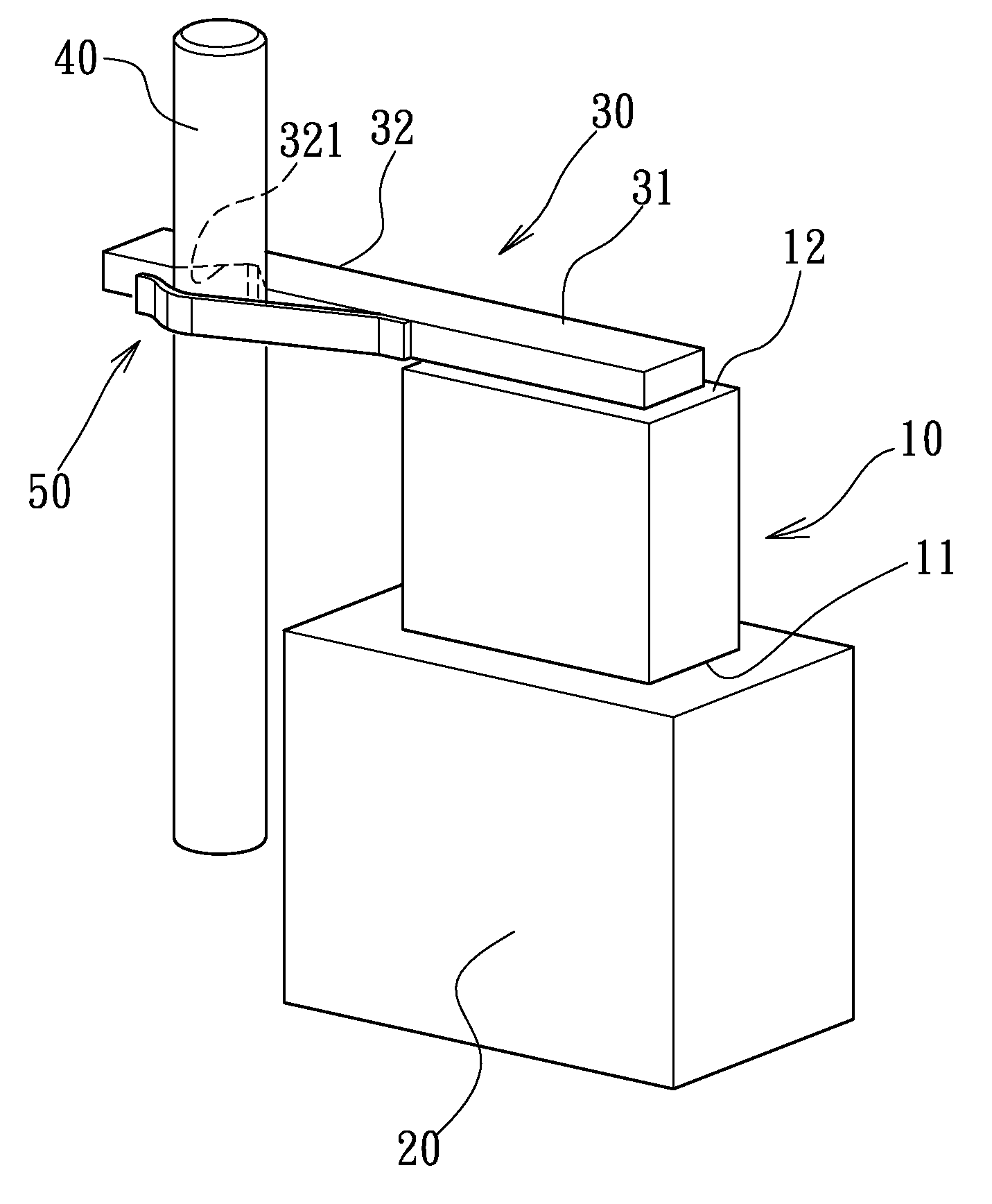
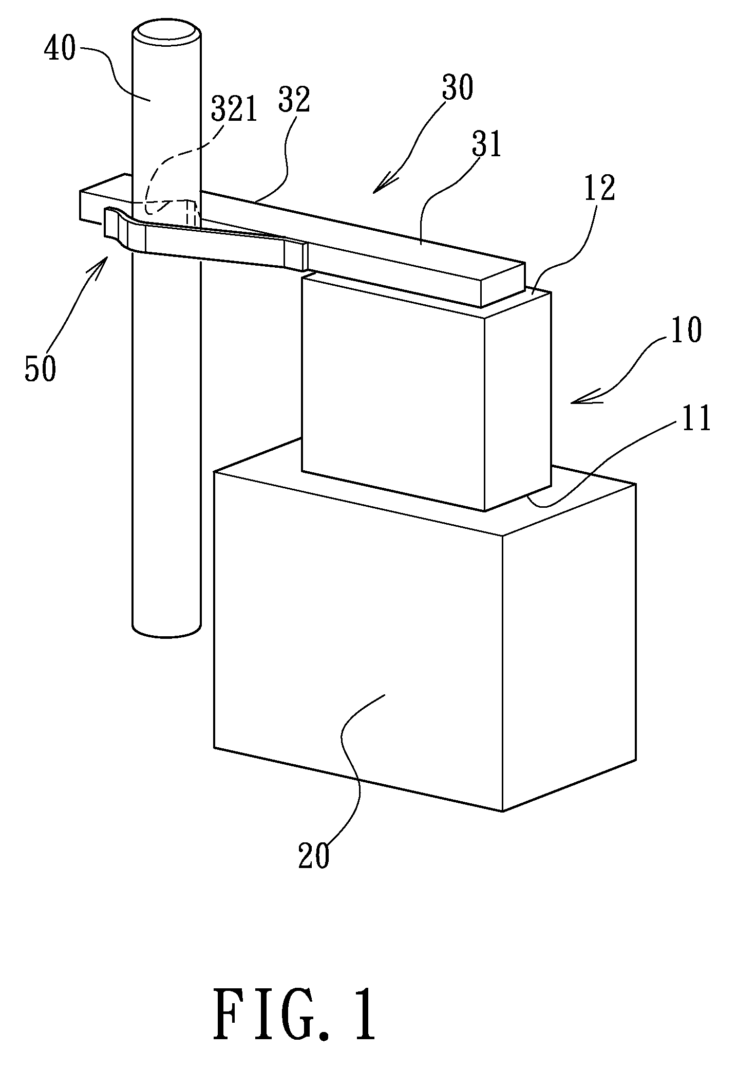
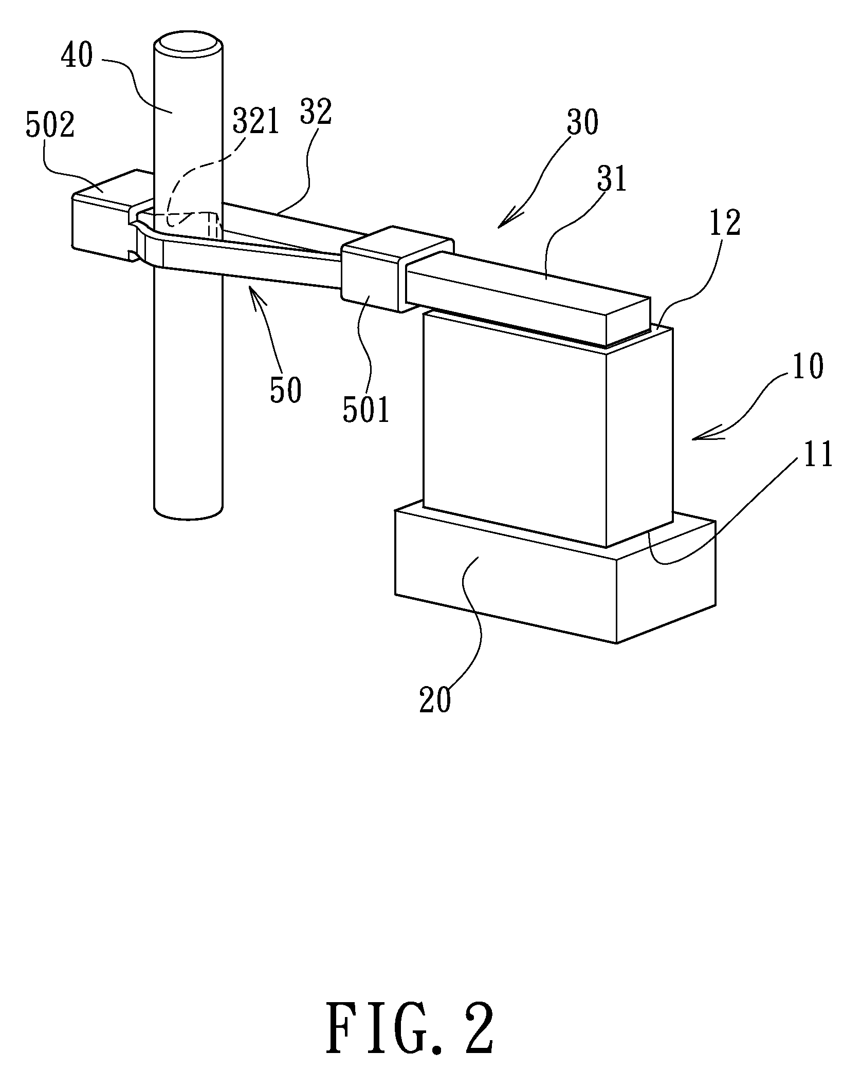
[0025] Referring to FIG. 1, an electromechanical actuator structure in accordance with an embodiment of the present invention is shown comprising an electric actuator 10. The electric actuator 10 has a bottom side 11 connected to a fixed base 20, and a top side 12 connected to a rear fixed segment 31 of a resilient drive member 30.

[0026] The resilient drive member 30 has a front resilient segment 32 forwardly extending from the rear fixed portion 31 out of the electric actuator 10. When the electric actuator 10 drives the rear fixed segment 31 to displace, the front resilient segment 32 produces a greater amplitude of oscillation relative to the rear fixed segment 31 due to the effect of its resilient material property, thereby amplifying the amount of displacement of the rear fixed segment 31 (i.e., the amount of displacement of the electric actuator 10). The front resilient segment 32 has a front end terminating in a conduction portion 321. The conduction portion 321 is preferabl...


PUM


Abstract

An electromechanical actuator structure is disclosed to include an electric actuator affixed to a base, a resilient drive member, which has a fixed segment fixedly connected to the electric actuator for synchronous reciprocating movement and a resilient segment extending out of the electric actuator and terminating in a conduction portion, a passive member mounted in the conduction portion of the resilient drive member, and a spring member mounted on the resilient segment of the resilient drive member and forcing the passive member into friction engagement with the conduction portion for enabling the passive member to be moved with the resilient drive member. By means of the amplitude of oscillation produced by the resilient drive member during displacement, the amount of displacement of the passive member is enlarged, and therefore the displacement speed of the passive member is increased and the working frequency of the drive pulse is lowered.

Description

BACKGROUND OF THE INVENTION [0001] 1. Field of the Invention [0002] The present invention relates to an electromechanical actuator and more particularly, to an electromechanical actuator structure practical for use in a flat, small-sized product, such as a lens or image sensor of a mobile electronic product having a photographing function. This increases the displacement speed of the passive member and lowers the working frequency of the drive pulse by the use of an electric actuator to produce a displacement action and the use of a resilient drive member to increase the amount of displacement of the electric actuator to the passive member. [0003] 2. Description of the Related Art [0004] U.S. Pat. No. 6,218,764, entitled “Actuator using electromechanical transducer and drive pulse generator suitable thereof”, discloses an actuator using an electromechanical transducer capable of driving efficiently and at high speed, which comprises an electromechanical transducer for repeatedly pro...

Claims


Application Information

Patent Timeline
Patent Type & Authority Applications(United States)
IPC IPC(8): H02N2/00
CPCH02N2/025
Inventor LEI, SIO-HOUPAN, WEN-SENWANG, KAI-LU
Owner TAIWAN ADVANCED MATERIALS TECH CORP
Why Eureka
Try Eureka