Multiple mode display device

a display device and multi-mode technology, applied in the field of multi-mode display devices, can solve the problems of limited viewing experience, inability to make autostereoscopic images appear very far off the screen, and cumbersome selection devices for proper stereoscopic use,

Inactive Publication Date: 2007-08-02
REAID INC
View PDF15 Cites 82 Cited by
  • Summary
  • Abstract
  • Description
  • Claims
  • Application Information

AI Technical Summary

Benefits of technology

[0015] According to a second aspect of the present design, there is provided a multiple mode display arrangement comprising a lens sheet comprising a plurality of individual lenticules forming a lenticular s

Problems solved by technology

Problems exist in single stereoscopic mode television designs that can result in a limited viewing experience, since stereoscopic content may be optimized for one kind of selection technique.
Autostereoscopic images often cannot make images appear to be very far off the screen without loosing sharpness whereas plano-stereoscopic images can.
Required selection devices (such as selection device eyewear, e.g. glasses) for proper stereoscopic can be cumbersome from a viewer point of view.
In the home environment, viewers wearing appropriate eyewear can impede or completely prevent people from performing normal daily tasks.
Repeatedly having to put the glasses on and then having to take them off can create a vexing experience for many observers, especially when one considers how easily devices of this kind are lost.
Consider television remote controls, whose disappearance is freque

Method used


Image

  • Multiple mode display device
  • Multiple mode display device
  • Multiple mode display device

Examples


Embodiment Construction

[0027] Reference will now be made in detail to the preferred designs of the invention, examples of which are illustrated in the accompanying drawings and tables. While the invention will be described in conjunction with the preferred designs, it will be understood that they are not intended to limit the invention to those designs. On the contrary, the invention is intended to cover alternatives, modifications, and equivalents, which may be included within the spirit and scope of the invention as defined by the appended claims.

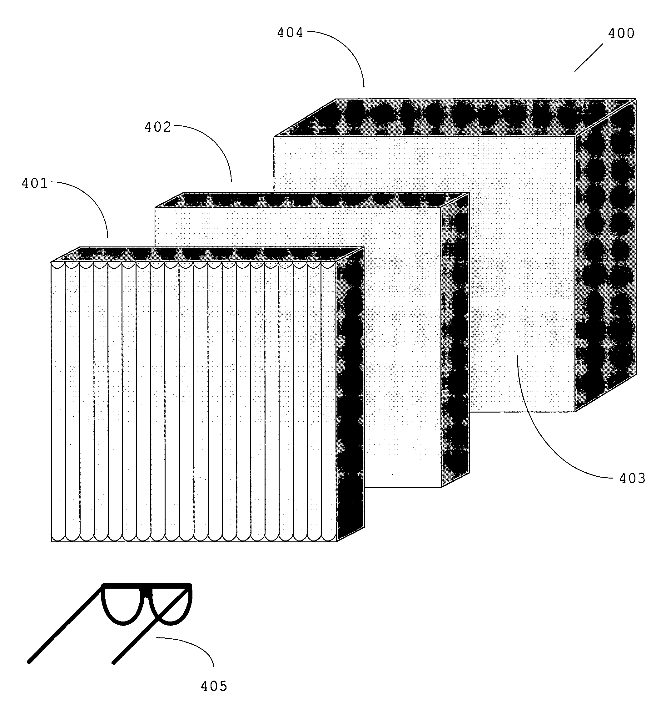
[0028] The present design provides a system and method for a multi-mode stereoscopic television set display device able to receive, process and render planar, plano-stereoscopic, and autostereoscopic images. The present design is described using an exemplary flat panel display device employing liquid crystal or plasma screen technologies. Use of the term “television set display device”, “flat panel display device”, or “display device” is in no way intended to ...


PUM


Abstract

An apparatus comprising a selection device and a multiple mode display device is disclosed. The multiple mode display device comprises a lens sheet comprising a plurality of individual lenticules forming a lenticular surface, an electro-optical modulator positioned adjacent the lens sheet, and a display device comprising a display surface. Alternatively, a multiple mode display arrangement is disclosed, comprising a lens sheet comprising a plurality of individual lenticules forming a lenticular surface and a display device comprising a display surface. The display device is positioned behind the lens sheet, thereby enabling viewing images transmitted in at least a planar mode and a stereoscopic mode.

Description

BACKGROUND OF THE INVENTION [0001] 1. Field of the Invention [0002] The present invention relates in general to receiving, processing, and rendering two-dimensional and three-dimensional images, and more specifically a novel television set that operates in multiple image presentation modes able to render planar, stereoscopic, and / or autostereoscopic images. [0003] 2. Description of the Related Art [0004] Current television sets serve a wide variety of purposes and display images with different formats. Many of today's television sets are able to display National Television System Committee (NTSC) images, high-definition television (HDTV) images, and digital images originating from a computer, digital camera, or other image capture devices. To properly display each of these image types, television sets may support a wide range of image resolutions and different aspect ratios. Often only a portion of the television display screen contains a viewable image since the very shape of the i...

Claims


Application Information

Patent Timeline
IPC IPC(8): H04N13/04G02B30/25
CPCH04N13/0404H04N13/0438H04N13/0434H04N13/305H04N13/337H04N13/341
Inventor LIPTON, LENNYGREER, JOSH
Owner REAID INC
Why Eureka
Try Eureka