
Method and Apparatus for Completing a Horizontal Well

a horizontal well and well drilling technology, applied in the field of horizontal well drilling, can solve the problems of high voltage, high cost and slow logging procedures, and the present of a cased horizontal well logged

Active Publication Date: 2007-08-09
TOLSON JET PERFORATORS
View PDF13 Cites 75 Cited by
  • Summary
  • Abstract
  • Description
  • Claims
  • Application Information

AI Technical Summary

Benefits of technology

[0009]In this invention, the operator runs and cements a conduit, such as a liner or casing in a wellbore. The operator then forms one or more displacement perforations through the conduit and surrounding cement and into an earth formation. He then pumps down a wireline logging to

Problems solved by technology

Logging a cased horizontal well presents a problem, because gravity won't pull the tool down.
Generally, these logging procedures are expensive and slow.
Also, high voltages are typically required, which can be detrimental to the wireline.
Consequently, pump-down logging is normally not performed on horizontal wells.

Method used


Image

  • Method and Apparatus for Completing a Horizontal Well
  • Method and Apparatus for Completing a Horizontal Well
  • Method and Apparatus for Completing a Horizontal Well

Examples


Embodiment Construction

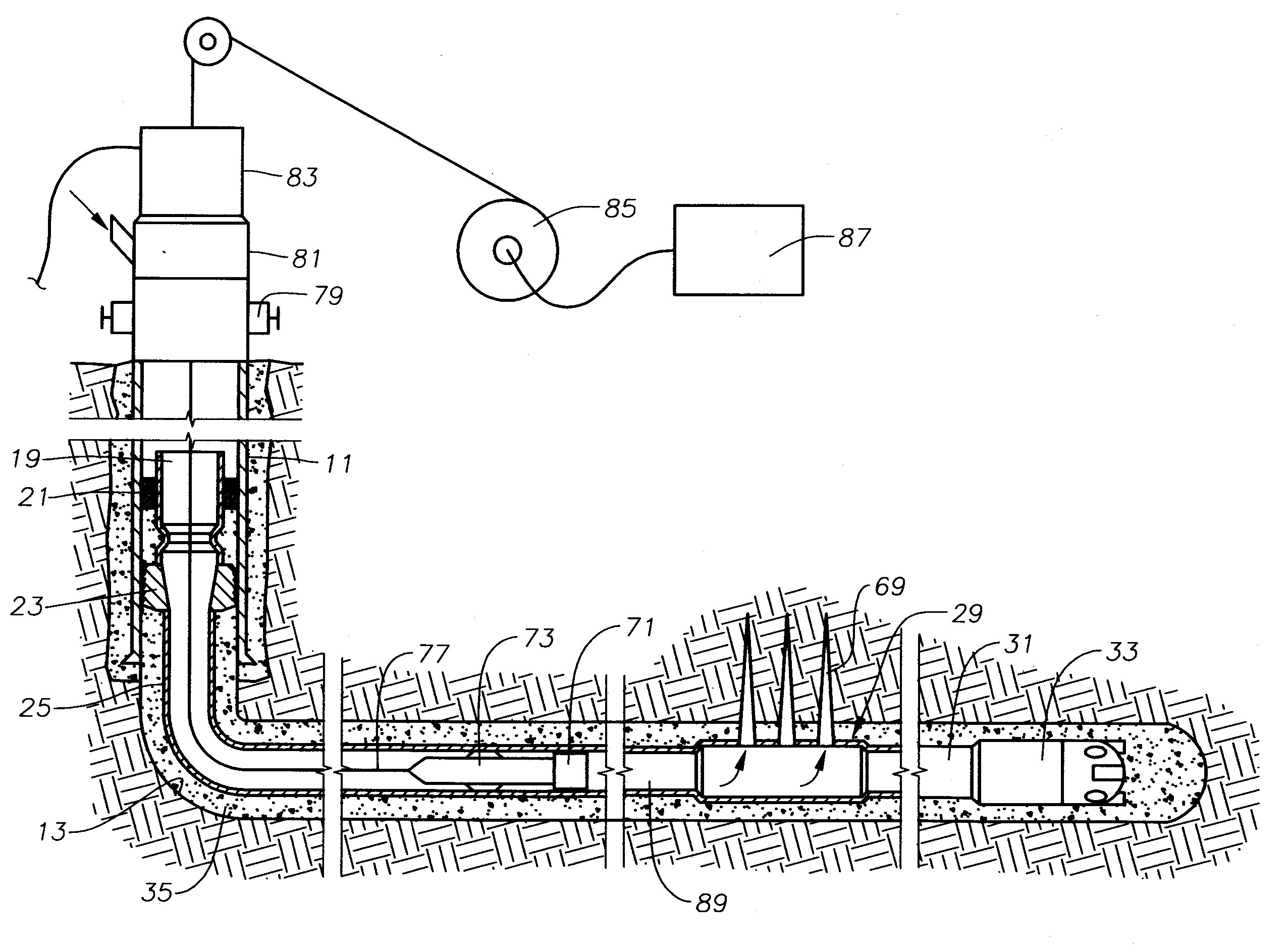
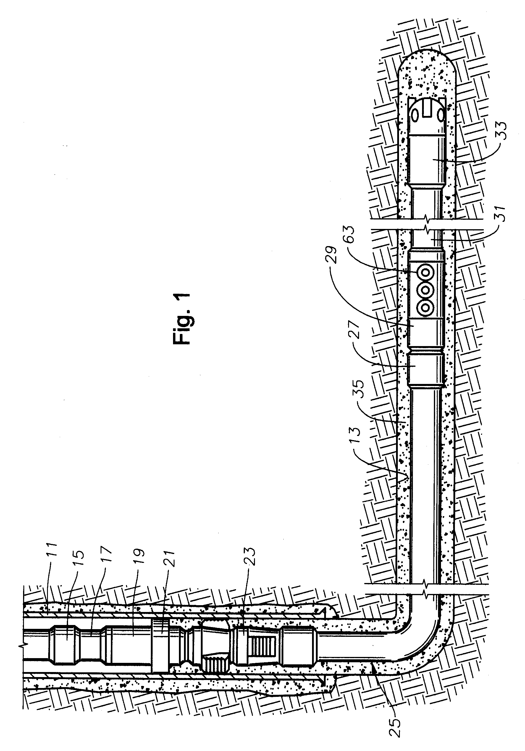
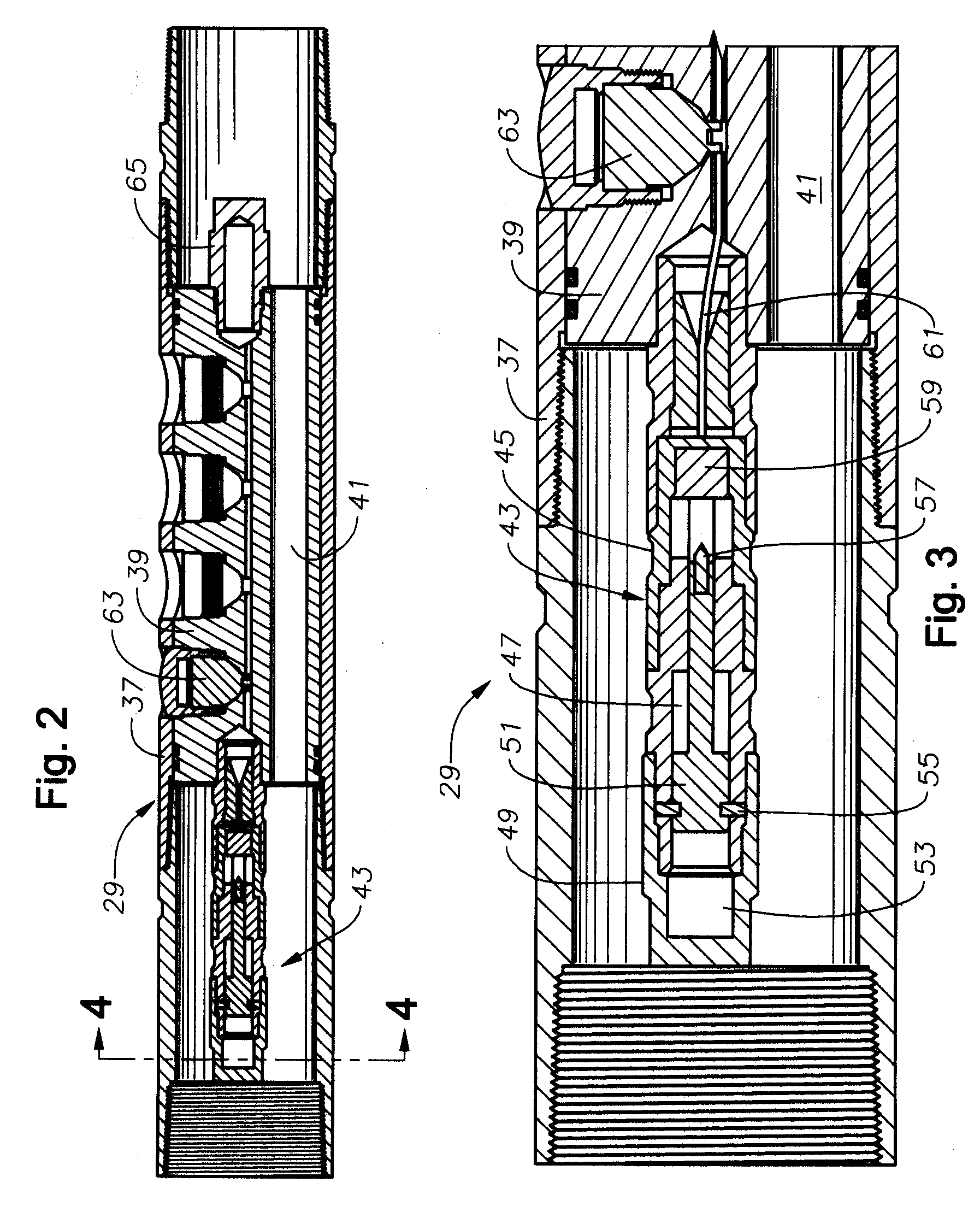
[0022]Referring to FIG. 1, the well has a vertical section with a conventional string of casing 11 that is cemented in place. The operator has drilled an open hole section 13 below casing 11 open hole section 13 having a substantially horizontal portion that may extend thousands of feet. In the embodiment of FIG. 1, a string of drill pipe 15 is shown extending into the casing 11. A setting tool 17 is located on the lower end of drill pipe 15. Setting tool 17 is connected to a tieback extension 19, which in turn is connected to a packer 21. Packer 21 is connected to a liner hanger 23. A liner 25 is secured to liner hanger 23 for securing the upper end of liner 25 to the inner diameter of casing 11. Liner 25 is a string of casing smaller in diameter than the casing 11. Rather than having its upper end near the lower end of casing 11, liner 25 could have its upper end at the surface. Liner 25 is shown in the process of being installed with its upper end a short distance above the lower...


PUM


Abstract

A firing head assembly has a sealed chamber containing a piston, a firing pin, and an impact detonator. The firing head assembly and a perforating charge are installed within a sub and the sub is secured into a string of conduit being lowered into a wellbore. After cementing the conduit, the operator drills out the cement in the conduit, disintegrating the chamber and exposing the sealed chamber to the fluid pressure of the drilling fluid in the conduit. The drilling fluid pressure causes the piston to drive the firing pin against the detonator, which detonates the perforating charge. The operator then pumps down a logging tool to survey the well. Fluid in the conduit below the pump-down head can flow out the displacement perforation into the earth formation while the logging tool is moving downward.

Description

CROSS-REFERENCE TO RELATED APPLICATION[0001]This application claims priority to provisional application 60 / 771,593, filed Feb. 8, 2006.FIELD OF THE INVENTION[0002]This invention relates in general to oil and gas well drilling and in particular to a method of completing a horizontal well that enables a wireline well tool to be pumped down a liner.BACKGROUND OF THE INVENTION[0003]Highly deviated or horizontal wells are commonly drilled for oil and gas production. As used herein, the term “horizontal” refers to not only wells with truly horizontal sections, but also to wells that are highly deviated. In one type of horizontal well completion, the operator installs and cements a casing or liner that extends to the total depth of the well. Normally, the term “casing” refers to conduit that extends back to the surface wellhead, and “liner” refers to conduit that has its upper end supported near the lower end of a first string of casing. These terms will be used interchangeably herein to r...

Claims


Application Information

Patent Timeline
IPC IPC(8): E21B43/117
CPCE21B23/08
Inventor RANKIN, E. EDWARDHAWTHORNE, LLOYD A.
Owner TOLSON JET PERFORATORS
Learn More