
Stator

a technology of stator and spherical rod, which is applied in the direction of dynamo-electric machines, electrical apparatus, supports/enclosements/casings, etc., can solve the problem of difficult to set the location of connecting wires, and achieve the effect of convenient arrangemen

Active Publication Date: 2007-08-09
DENSO CORP
View PDF5 Cites 52 Cited by
  • Summary
  • Abstract
  • Description
  • Claims
  • Application Information

AI Technical Summary

Benefits of technology

[0004] An objective of the present invention is to provide a stator that permits connecting wires to be easily arranged.

Problems solved by technology

It is troublesome, however, to contain the connecting wires in the respective corresponding outer circumferential grooves, and it is also difficult to set the location of the connecting wires.

Method used


Image

  • Stator
  • Stator
  • Stator

Examples


first embodiment

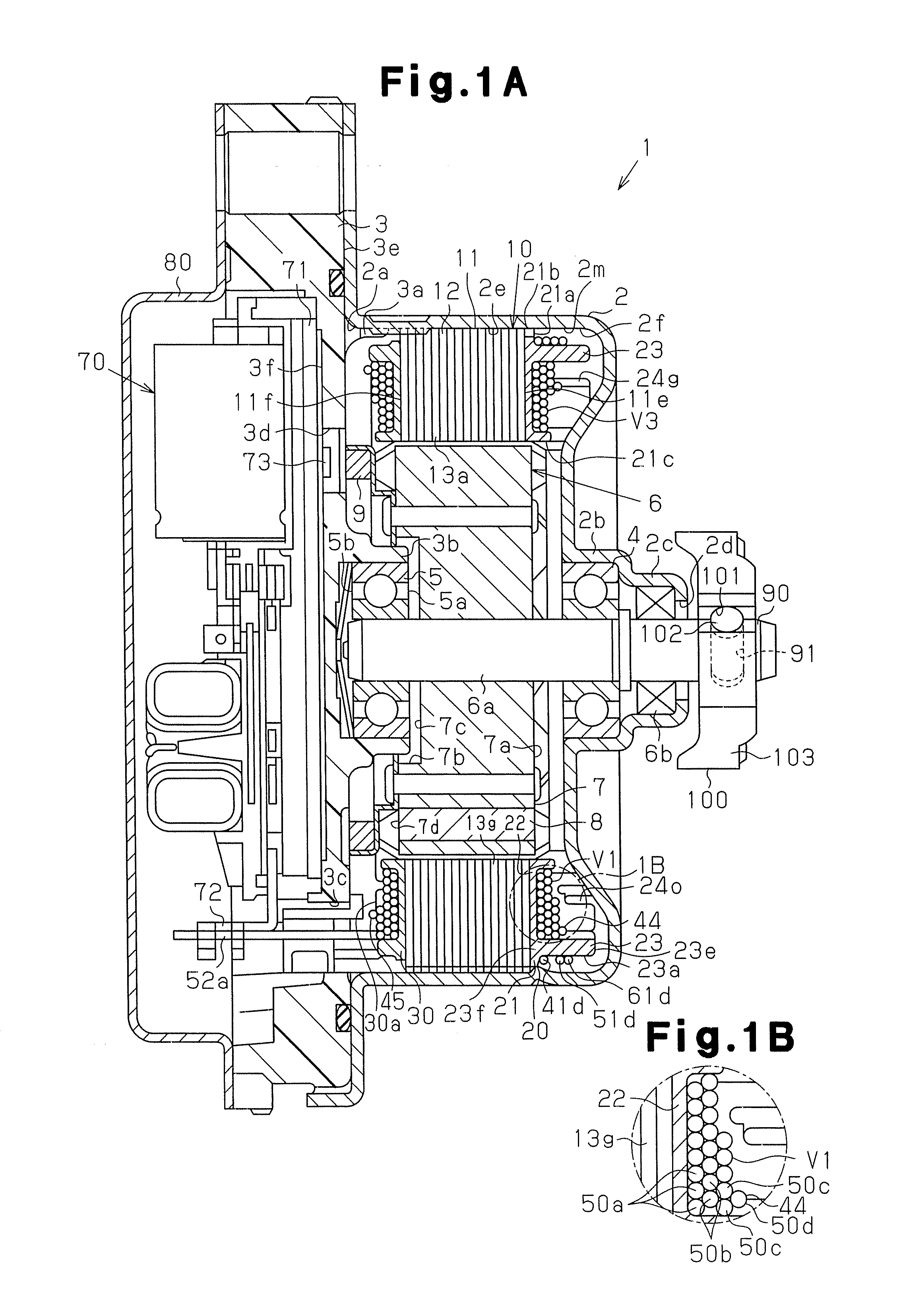
[0026] In the following, the present invention is described in reference to FIGS. 1A to 6.

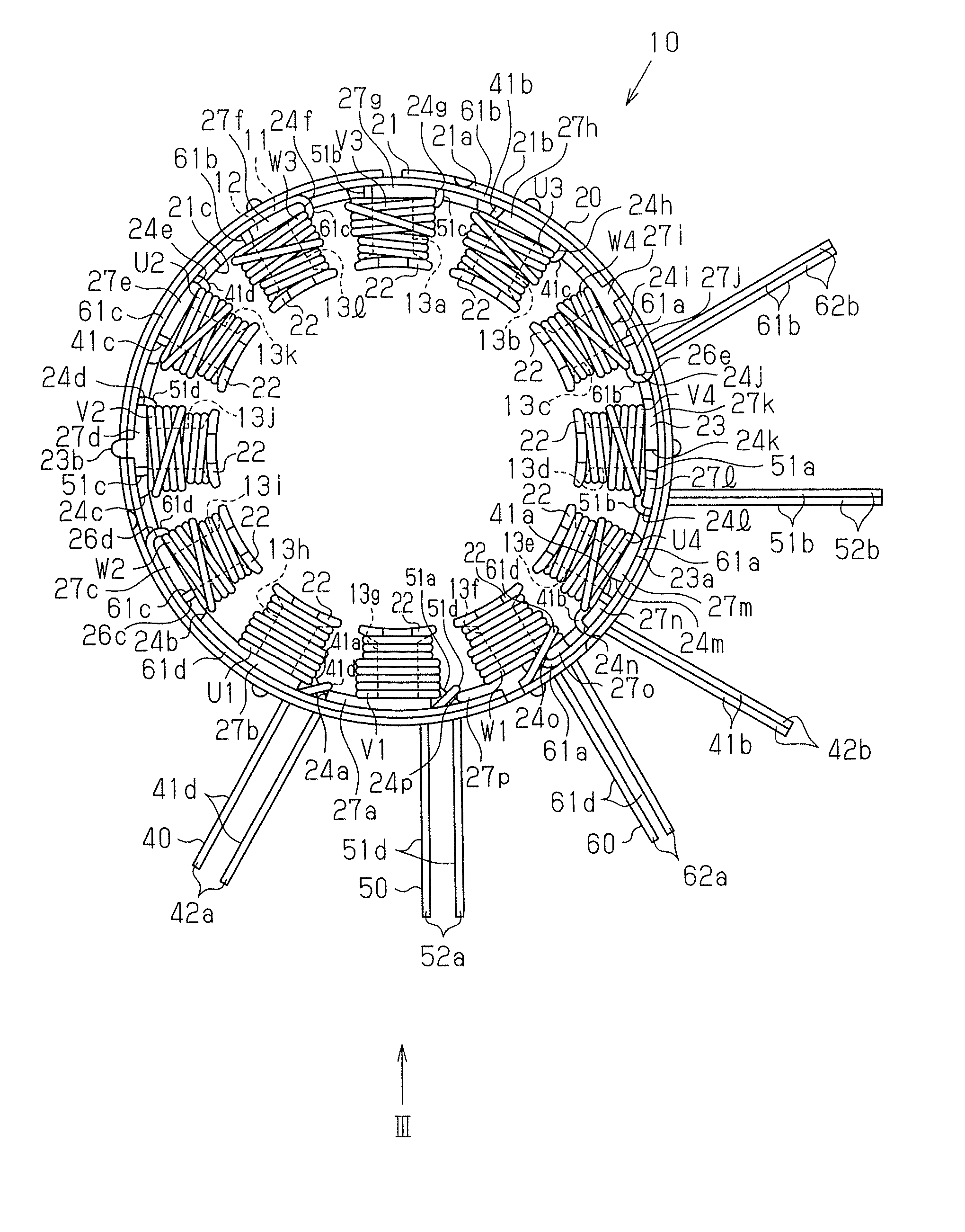
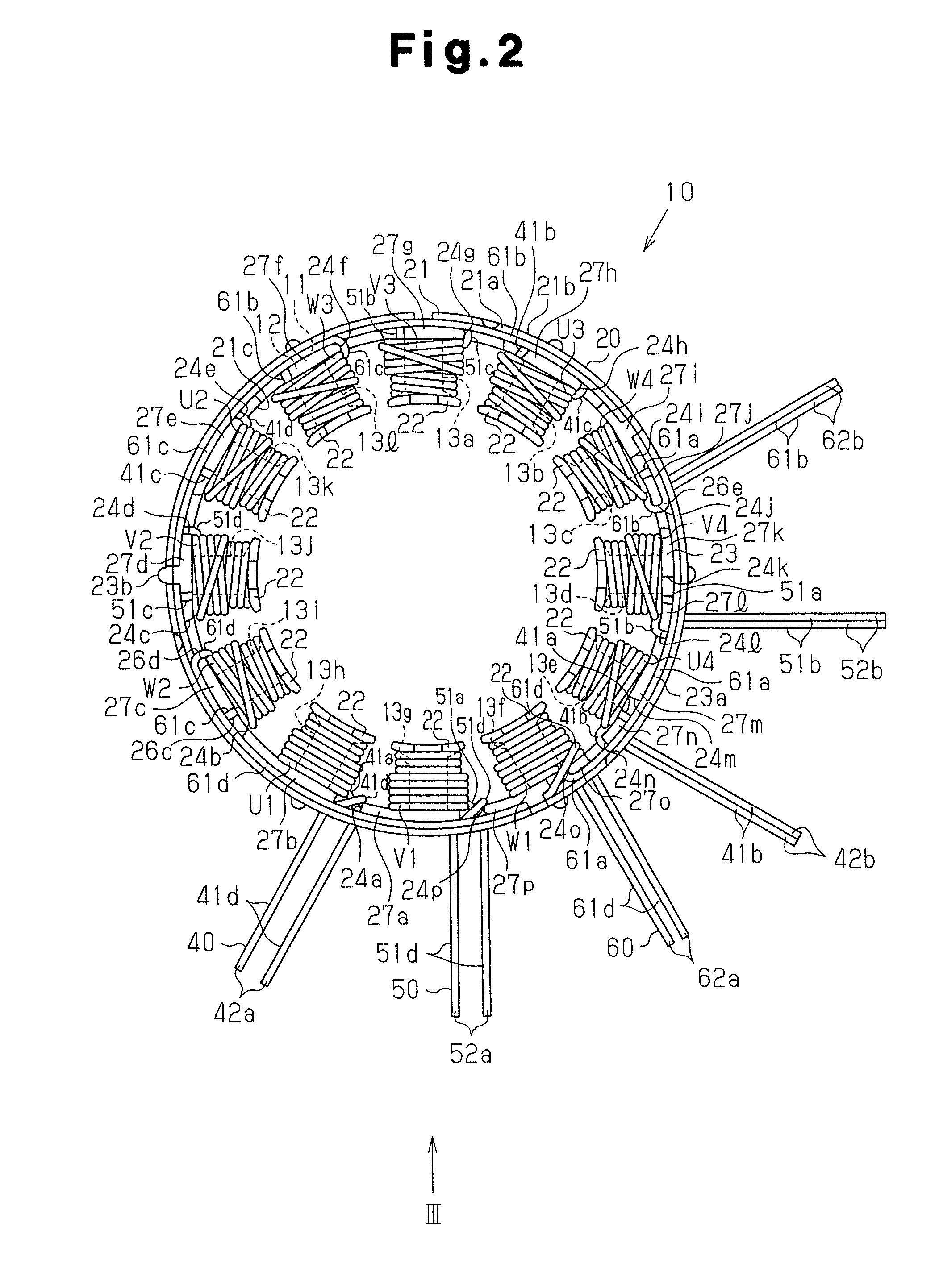
[0027]FIG. 1A shows an inner rotor type brushless motor 1 according to the first embodiment. The brushless motor 1 has a housing 2 in the form of a cylinder having a bottom, a stator 10 in cylindrical form which is press fitted in the housing 2, and a rotor 6 which is contained inside the stator 10 in the radial direction in such a manner as to be rotatable. The stator 10 makes contact with the cylindrical wall 2e of the housing 2. The stator 10 faces the outer circumferential surface of the rotor core 7.

[0028] An opening 2a of the housing 2 is closed by an end frame 3. The end frame 3 has an engaging portion which engages with the opening 2a from the inside. The end frame 3 has a first surface 3e which faces the stator 10 and a second surface 3f which faces the direction opposite to the stator 10.

[0029] As shown in the right in FIG. 1A, a first containing portion 2b for containing a first be...

second embodiment

[0119] In the following, the present invention is described in reference to FIGS. 7A, 7B and 8.

[0120] The fifteenth engaging protrusion 27o has a sixth side surface 26f in a fifteenth notch 24o. The sixteenth engaging protrusion 27p has a seventh side surface 26g in the fifteenth notch 24o.

[0121] The twelfth connecting wire 61d is bent at the fifteenth notch 24o to an angle which exceeds 90°. The ninth connecting wire 61a is bent at the fifteenth notch 24o to an angle which exceeds 90°.

[0122] In detail, the twelfth connecting wire 61d is bent in a plane which is vertical to the axial direction to an angle which exceeds 90°. The sixth side surface 26f is at a distance from the side surface of the ninth coil W1 in the circumferential direction. Accordingly, the twelfth connecting wire 61d extends from the ninth coil W1 to the fifteenth notch 24o in the circumferential direction and is bent around the sixth side surface 26f to an angle of 180°, and thus, passes through the fifteenth ...


PUM


Abstract

A connecting wire extends from a first tooth to a second tooth so as to connect a plurality of coils. An extension portion is provided to an insulator so as to extend in the axial direction. The extension portion has a distal end in the axial direction, a proximal end, notches which extend from the distal end to the proximal end, and a radially outer surface. The connecting wire extends from the first tooth and is positioned by the bottom surface and the side surfaces of a notch. The connecting wire is led out from the notch in the radial direction of the extension portion, and arranged along the radially outer surface so as to run toward the second tooth. Accordingly, the connecting wire can be arranged with ease.

Description

BACKGROUND OF THE INVENTION [0001] The present invention relates to a stator. [0002] Japanese Laid-Open Patent Publication 11-55883 discloses a stator which is used for a brushless motor. A plurality of outer circumferential grooves are created so as to extend in the circumferential direction on the outer circumferential surface of an insulator which is attached to this stator. A plurality of connecting wires are contained in the respective corresponding outer circumferential grooves. Each connecting wire connects a coil to another coil. [0003] It is troublesome, however, to contain the connecting wires in the respective corresponding outer circumferential grooves, and it is also difficult to set the location of the connecting wires. SUMMARY OF THE INVENTION [0004] An objective of the present invention is to provide a stator that permits connecting wires to be easily arranged. [0005] According to one aspect of the present invention, a stator having a stator core, an insulator and a ...

Claims


Application Information

Patent Timeline
Patent Type & Authority Applications(United States)
IPC IPC(8): H02K11/00H02K5/00H02K3/00
CPCH02K2203/06H02K3/522
Inventor MAKINO, TAKASHIFUJIYAMA, ATSUSHI
Owner DENSO CORP
Features
  • Generate Ideas
  • Intellectual Property
  • Life Sciences
  • Materials
  • Tech Scout
  • Unparalleled Data Quality
  • Higher Quality Content
  • 60% Fewer Hallucinations
Learn More