System and method for detecting and recovering from virtual switch link failures

a virtual switch and failure technology, applied in the field of computer networks, can solve problems such as time-consuming and error-pron

Active Publication Date: 2007-08-09
CISCO TECH INC
View PDF16 Cites 142 Cited by
  • Summary
  • Abstract
  • Description
  • Claims
  • Application Information

AI Technical Summary

Benefits of technology

[0008] Briefly, the invention relates to a system and method for detecting and responding to failures occurring in a virtual switch. A virtual switch is a logical representation of a plurality of physical switches as a single switch. The virtual switch is formed by interconnecting the physical switches via one or more Virtual Switch Links (VSLs). The physical switches communicate across the VSLs in order to elect one of them to be the active part of the virtual switch. The active part, also referred to as the Master Chassis, executes the bridging and routing protocols for the entire virtual switch. The non-elected parts of the virtual switch operate as standby parts, also referred to as Slave Chassis. In an illustrative embodiment,

Problems solved by technology

Each switch of a computer network generally requires some

Method used


Image

  • System and method for detecting and recovering from virtual switch link failures
  • System and method for detecting and recovering from virtual switch link failures
  • System and method for detecting and recovering from virtual switch link failures

Examples


Embodiment Construction

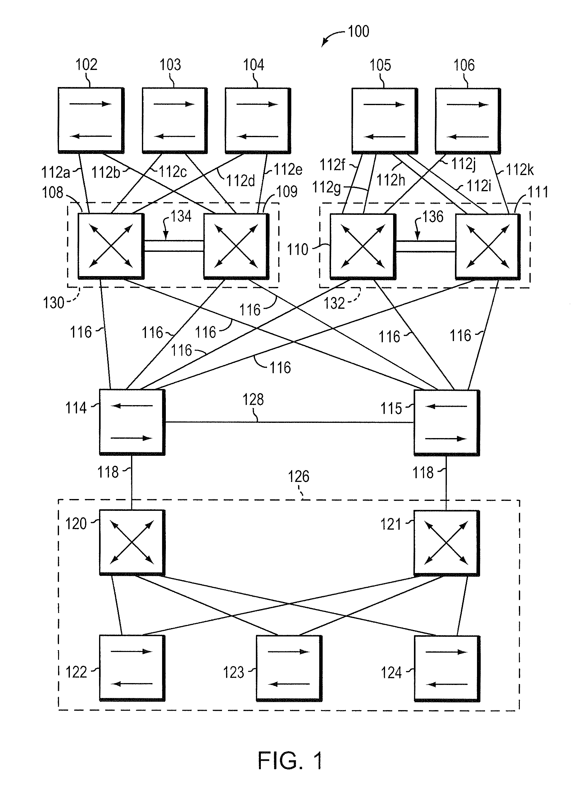
[0018]FIG. 1 is a highly schematic illustration of a computer network 100. The network 100 includes a plurality of access switches 102-106 that are coupled to four distribution switches 108-111 by corresponding uplinks 112a-k. The distribution switches 108-111, in turn, are coupled to a pair of core switches 114 and 115 by a plurality of links 116. The core switches 114 and 115 are coupled via trunks 118 to a group of distribution switches 120 and 121, and access switches 122-124 that may represent a data center 126. The two core switches 114 and 115 may be interconnected by a point-to-point link 128. Access switches 102-104 and 105-106 are typically disposed in respective wiring closets, and are each coupled to a plurality of local area networks (LANs) and end stations (not shown). The access switches 122-124 of the data center 126 are similarly coupled to data storage systems and / or other devices (not shown). The configuration of the network 100 allows the LANs and end stations co...


PUM


Abstract

A system and method detects and responds to failures occurring in a virtual switch. The virtual switch is formed from two or more physical switches interconnected by a Virtual Switch Link (VSL). One physical switch is elected the Master, and it executes a link aggregation protocol for the virtual switch. If the VSL fails, one of the other physical switches assumes that it should become the Master for the virtual switch, and it begins executing the link aggregation protocol. By adding information unique to the physical switches in the control packets of the link aggregation protocol, remote switches can identify when the VSL fails, and report this condition to the original Master. In response, the original Master or the new Master takes corrective action.

Description

BACKGROUND OF THE INVENTION [0001] 1. Field of the Invention [0002] The present invention relates generally to computer networks, and more specifically, to a method and apparatus for detecting and recovering from link failures. [0003] 2. Background Information [0004] Many organizations, including businesses, governments and educational institutions, utilize computer networks so that employees and others may share and exchange information and / or resources. A computer network typically comprises a plurality of entities interconnected by means of one or more communications media. An entity may consist of any device, such as a computer, that “sources” (i.e., transmits) or “sinks” (i.e., receives) messages over the communications media. A common type of computer network is a local area network (“LAN”) which typically refers to a privately owned network within a single building or campus. LANs typically employ a data communication protocol (LAN standard), such as Ethernet, or a wireless p...

Claims


Application Information

Patent Timeline
IPC IPC(8): H04J1/16
CPCH04L49/357H04L49/70H04L49/557H04L49/552
Inventor NARAYANAN, MANOJ T.HEBBAR, HEMANT K.PARAMESWARANNAIR, VINAYAKUMAR V.TAN, EDENSMITH, MICHAEL R.FINN, NORMAN W.
Owner CISCO TECH INC
Why Eureka
Try Eureka