Split skin dry-suit

Active Publication Date: 2007-08-16
WHITES MFG
View PDF13 Cites 11 Cited by
  • Summary
  • Abstract
  • Description
  • Claims
  • Application Information

AI Technical Summary

Benefits of technology

[0014]The elastomeric action of the second hollow elastic material can compress the underlying first element-proof fabric to provide a smooth body confirming dry-suit, and squeeze out any w

Problems solved by technology

Because excess fabric is used, the excess fabric tends to collect and crease at the flex points of the dry-suit such as the shoulders, armpits, neck, waist, knees and crotch areas.
This causes discomfort to the wearer of the dry-suit, especially at greater water depths where the hydrostatic water pressure forces the folds and creases against the body of the wearer at the respective flex points.
The accumulat

Method used


Image

  • Split skin dry-suit
  • Split skin dry-suit
  • Split skin dry-suit

Examples


Embodiment Construction

[0020]Throughout the following description specific details are set forth in order to provide a more thorough understanding to persons skilled in the art. However, well known elements may not have been shown or described in detail to avoid unnecessarily obscuring the disclosure. Accordingly, the description and drawings are to be regarded in an illustrative, rather than a restrictive, sense.

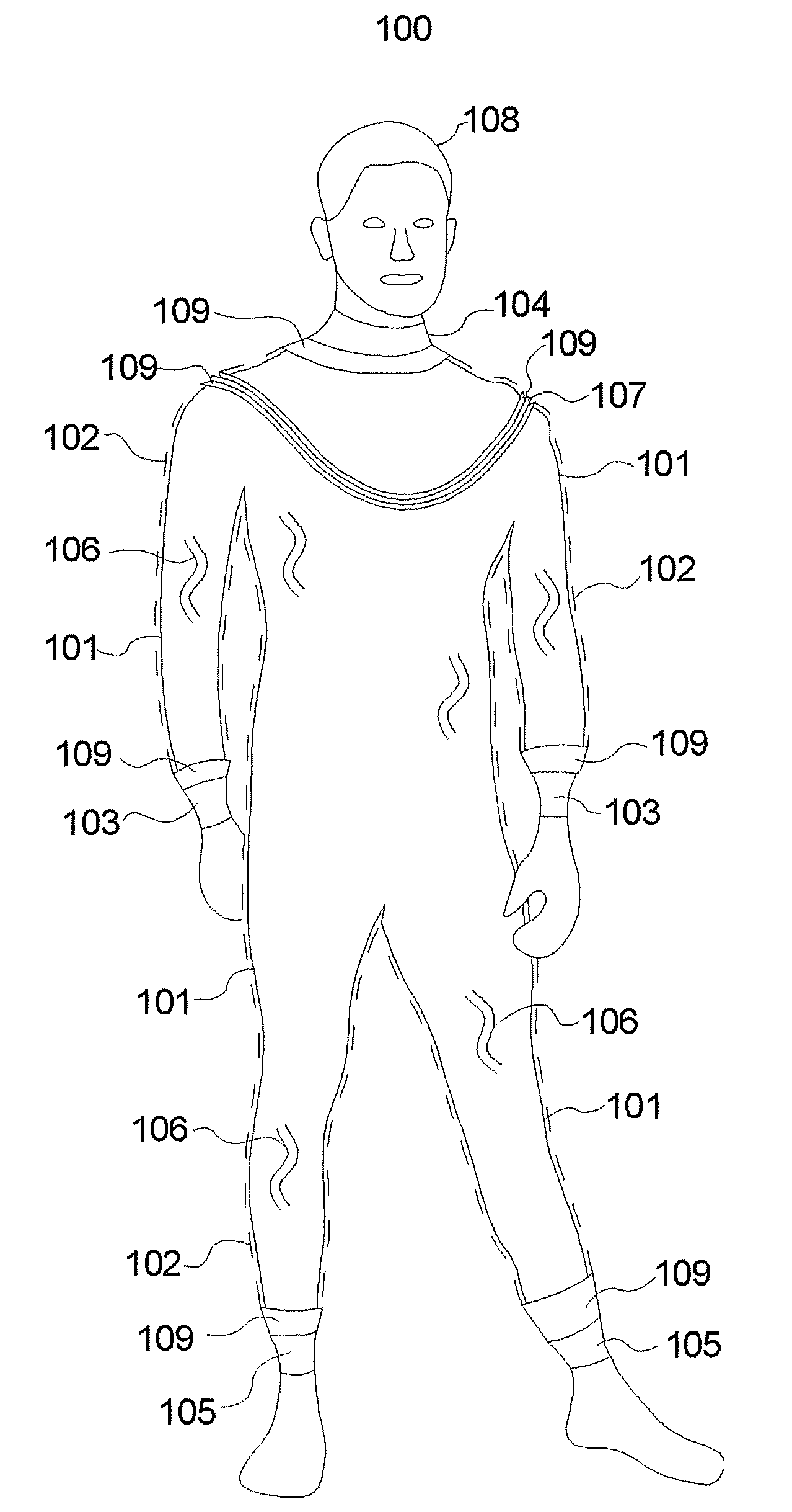
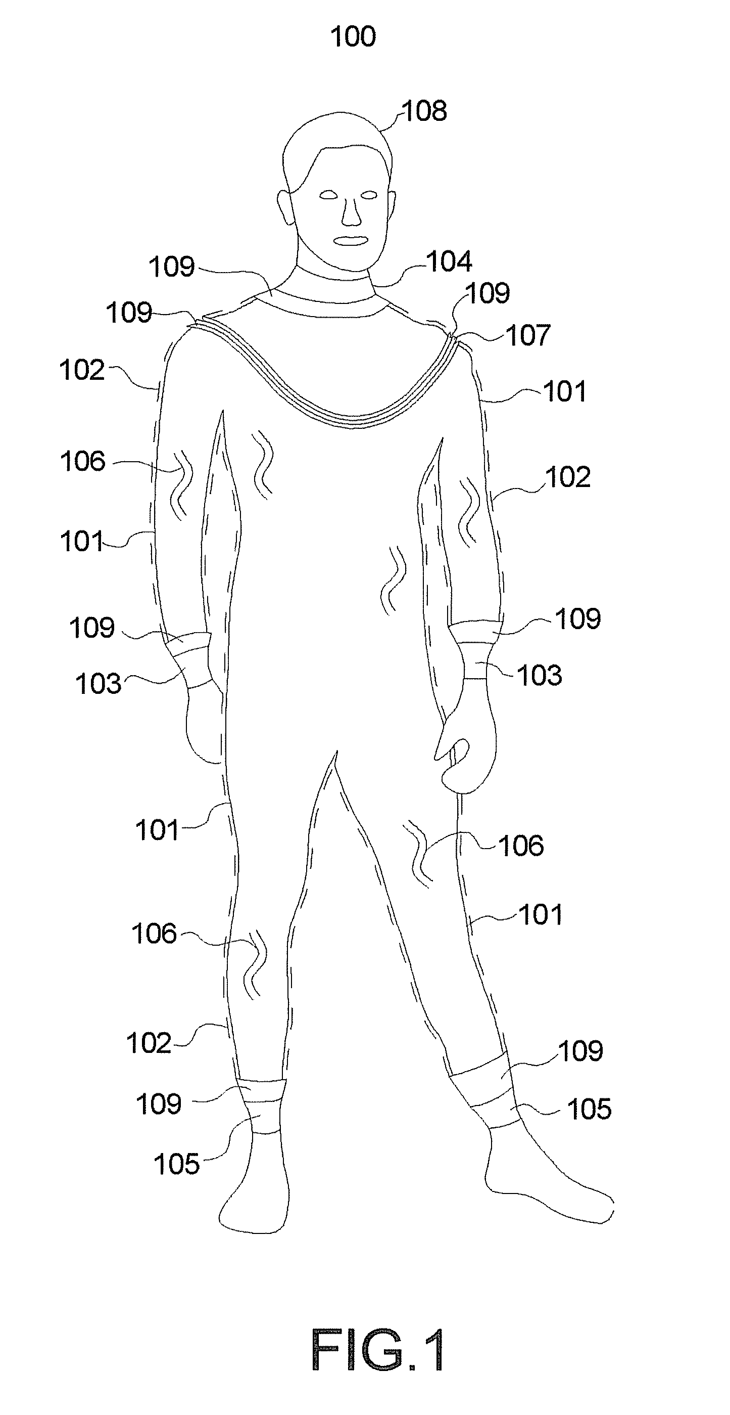
[0021]The subject invention discloses a novel design of a double layer dry-suit that closely fits the body of the wearer and allows increased mobility and comfort. This is a prime advantage because the reduction of bulky areas in the dry-suit, when in use, translates directly to the safety of the wearer. The outer surface of the dry-suit according to the invention is smooth and streamlined in construction compared to conventional bag style dry-suits. This minimizes motion resistance in the water. Swimming is easier and less effortful. The dry-suit according to the invention is typically used by d...


PUM


Abstract

This invention pertains to a novel dry-suit design that has a smooth elastomeric outer shell which envelopes a separate element proof inner shell. The dry-suit has a smooth integral outer appearance thereby enabling ready movement and comfortable use by a wearer.

Description

[0001]This application claims Convention priority on U.S. provisional patent application Ser. No. 60 / 772,864, filed Feb. 14, 2006.FIELD OF THE INVENTION[0002]This invention relates to a novel design of double layer (split-skin) dry-suit, useful for underwater diving or water surface activities.BACKGROUND OF INVENTION[0003]Fabric-based underwater diving or water surface activity dry-suits have been manufactured by the basic processes of heat seaming and stitching over several decades. To provide the user with ease of motion and the ability to access and remove the suits under severe conditions, dry-suits have traditionally been made from a bulky fabric that has an area that is well in excess of the area required to cover the body of the user. All seams of the dry-suit are sealed. Because excess fabric is used, the excess fabric tends to collect and crease at the flex points of the dry-suit such as the shoulders, armpits, neck, waist, knees and crotch areas. This causes discomfort to ...

Claims


Application Information

Patent Timeline
IPC IPC(8): A41D13/00
CPCA41D13/012B63C11/04A41D13/02A41D13/0125A41D31/065B63C2011/043
Inventor MYERSCOUGH, RICHARD KERR
Owner WHITES MFG
Why Eureka
Try Eureka