Angle adjusting assembly of stand tube
- Summary
- Abstract
- Description
- Claims
- Application Information
AI Technical Summary
Benefits of technology
Problems solved by technology
Method used
Image
Examples
Embodiment Construction
[0011] In order that those skilled in the art can further understand the present invention, a description will be described in the following in details. However, these descriptions and the appended drawings are only used to cause those skilled in the art to understand the objects, features, and characteristics of the present invention, but not to be used to confine the scope and spirit of the present invention defined in the appended claims.
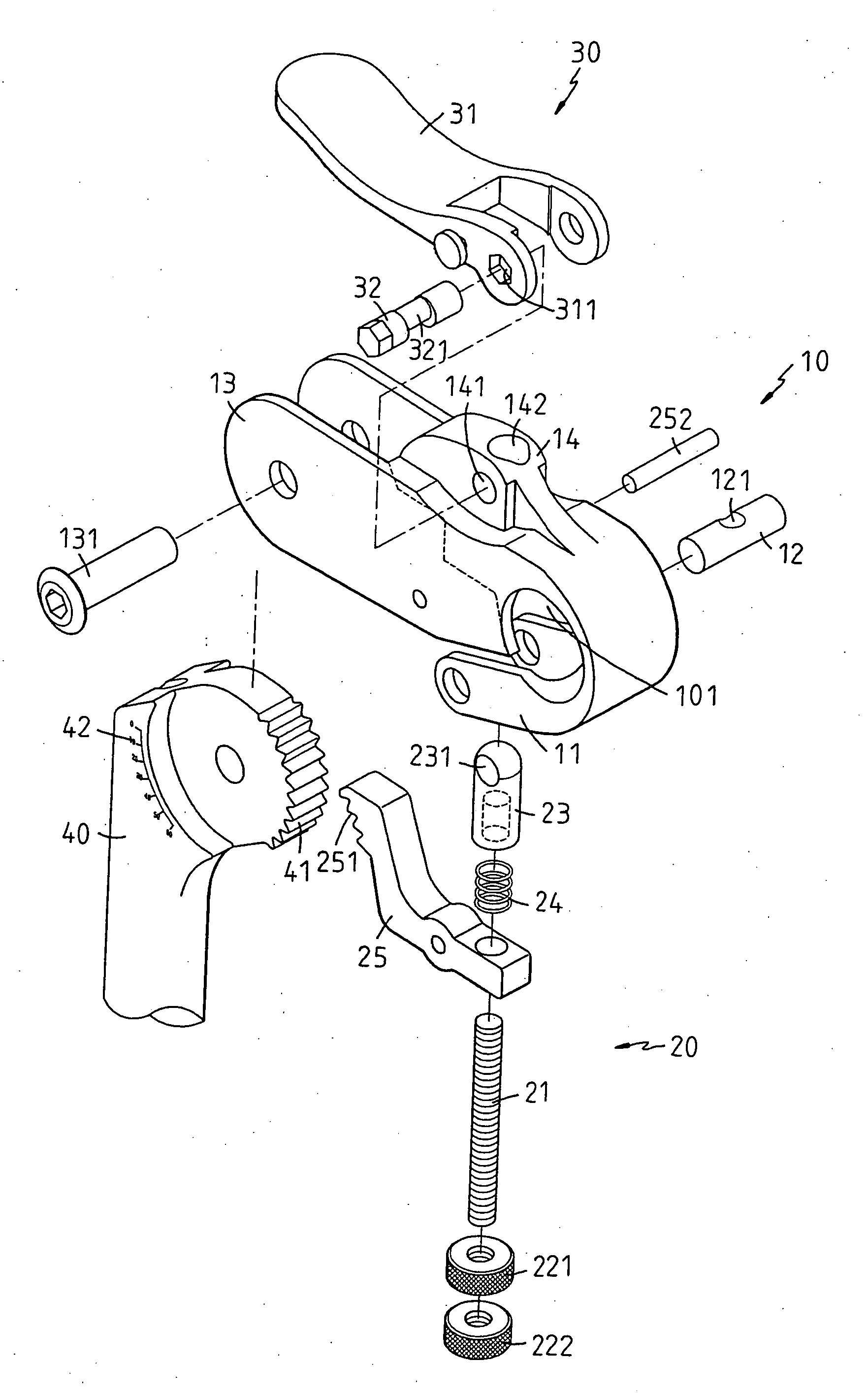
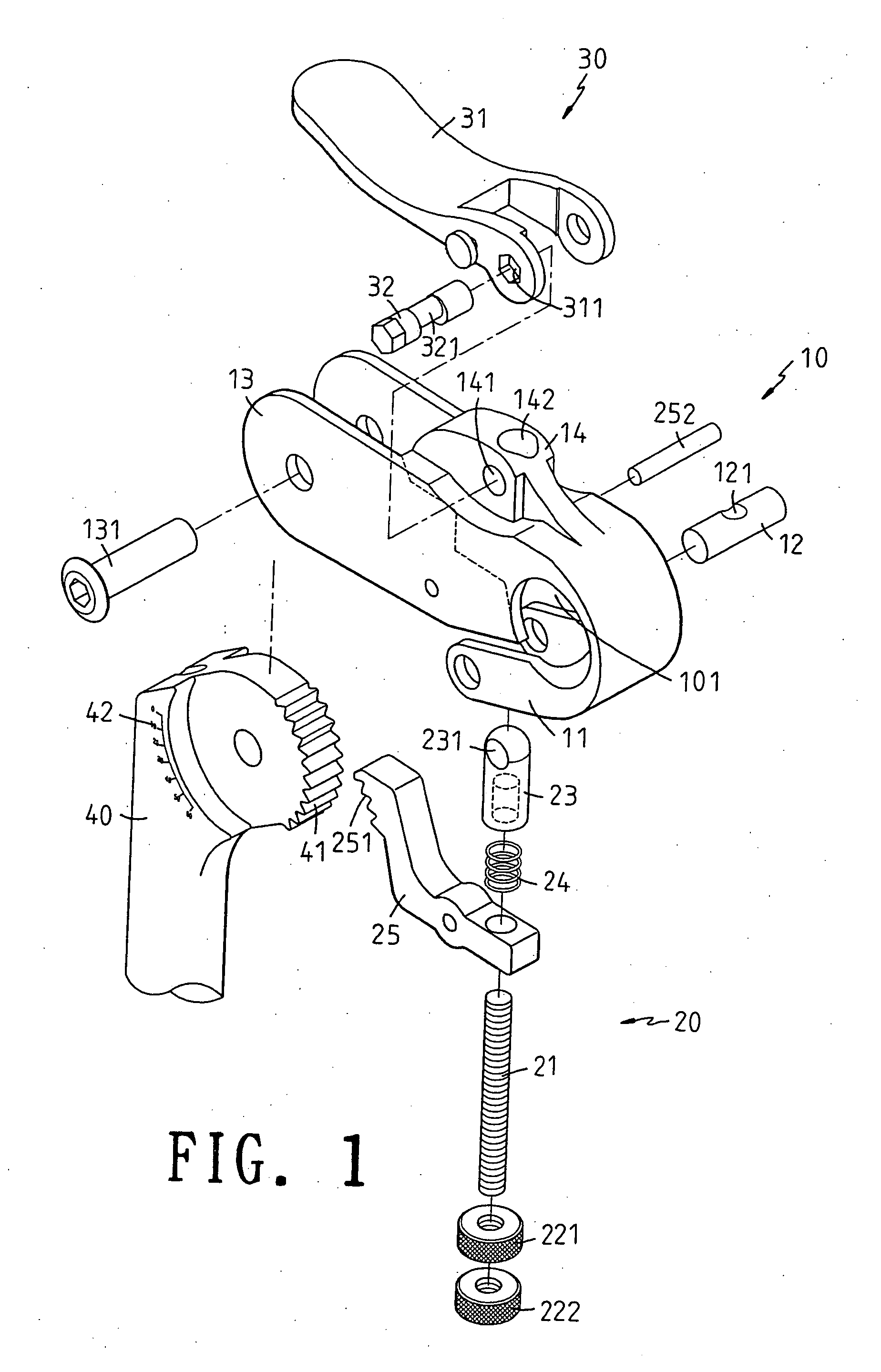
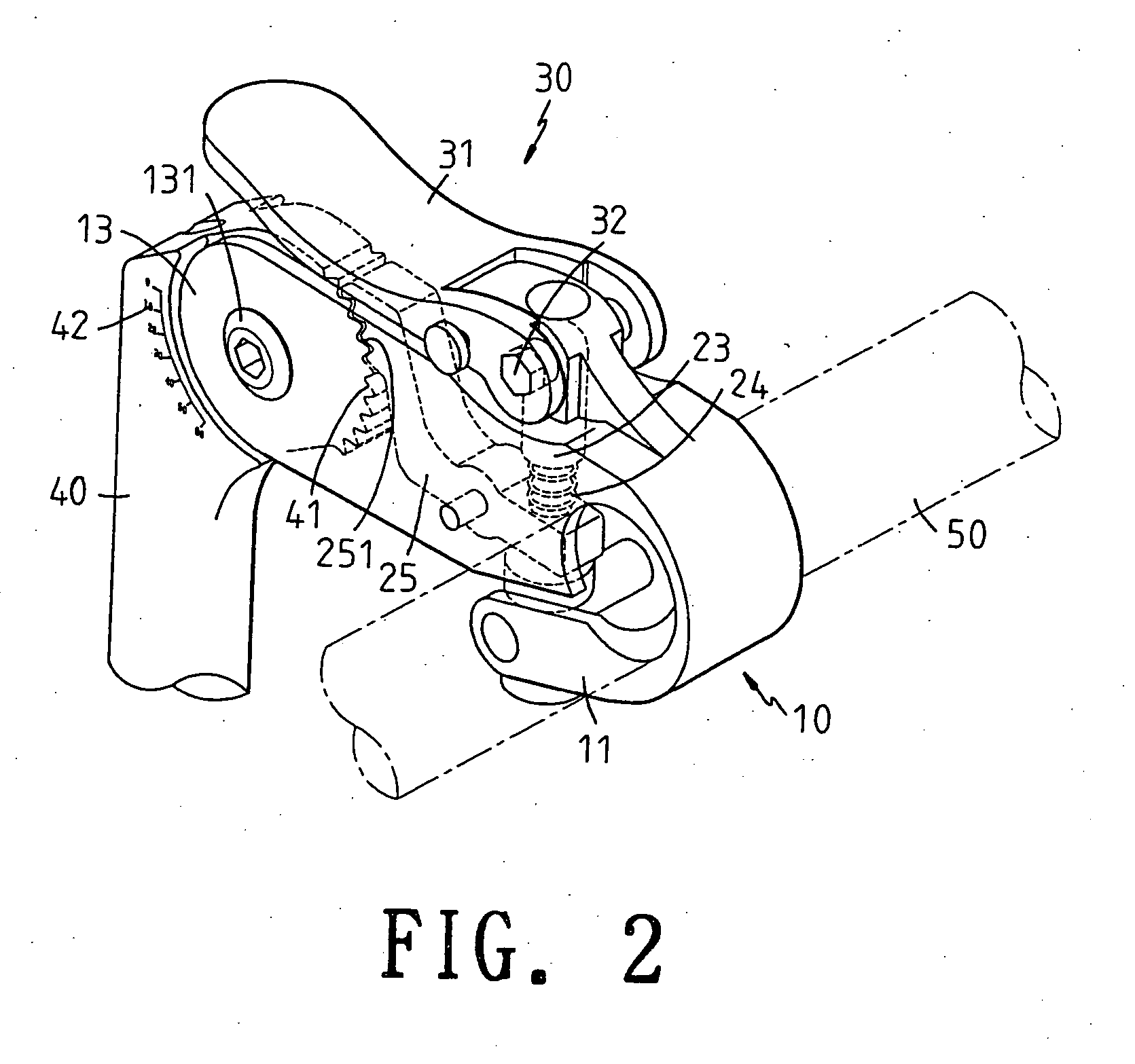
[0012] Referring to FIGS. 1 to 5, the angle adjusting assembly of a stand tube according to the present invention is illustrated. The present invention has the following element.
[0013] A stand tube 10 has a front end. An engaging hole 101 is formed at a front end. A handle 50 of a bicycle can be installed to the engaging hole 101. A lower end of the engaging hole 101 is formed with two wings 11. A penetrating unit 12 passes through the two wings 11. A penetrating hole 121 is installed in the penetrating unit 12. A rear end of the stand tube 10 ...
PUM
 Abstract
Description
Claims
Application Information
 - R&D
- Intellectual Property
- Life Sciences
- Materials
- Tech Scout
- Unparalleled Data Quality
- Higher Quality Content
- 60% Fewer Hallucinations
Browse by: Latest US Patents, China's latest patents, Technical Efficacy Thesaurus, Application Domain, Technology Topic, Popular Technical Reports.
© 2025 PatSnap. All rights reserved.Legal|Privacy policy|Modern Slavery Act Transparency Statement|Sitemap|About US| Contact US: help@patsnap.com


