
Headrest

Inactive Publication Date: 2015-11-05
TACHI S CO LTD
View PDF8 Cites 3 Cited by
  • Summary
  • Abstract
  • Description
  • Claims
  • Application Information

AI Technical Summary

Benefits of technology

The present invention is a headrest that is light but still safe and comfortable to touch. It provides a good feel to the area of the headrest that is meant to touch the passenger's head.

Problems solved by technology

However, the foam padding element having a low-repulsive elasticity used in the above-stated conventional headrest is so great in density as to increase the weight of that particular foam padding.
This raises the problem that the increased weight of the foam padding element requires a labor and hard handling on the side of a worker involved in assembling the headrest.
Further, another problem of this prior art is that such high-density foam padding element does exist as a hard layer limiting a distance or space between the trim cover assembly and the stay, which means that, in such limited space, the liquid foaming agent is cured and expanded to become the aforesaid normal-repulsive foam padding during a foaming process.
Consequently, adjustment for positioning the stay within the resulting foam padding is also limited due to the presence of the low-repulsive foam padding element, and therefore a freedom for positioning the stay within the headrest is limited.

Method used


Image

  • Headrest
  • Headrest
  • Headrest

Examples


Embodiment Construction

[0019]Hereinafter, with reference to the annexed drawings, a detailed description will be made of preferred embodiments of a headrest in accordance with the present invention.

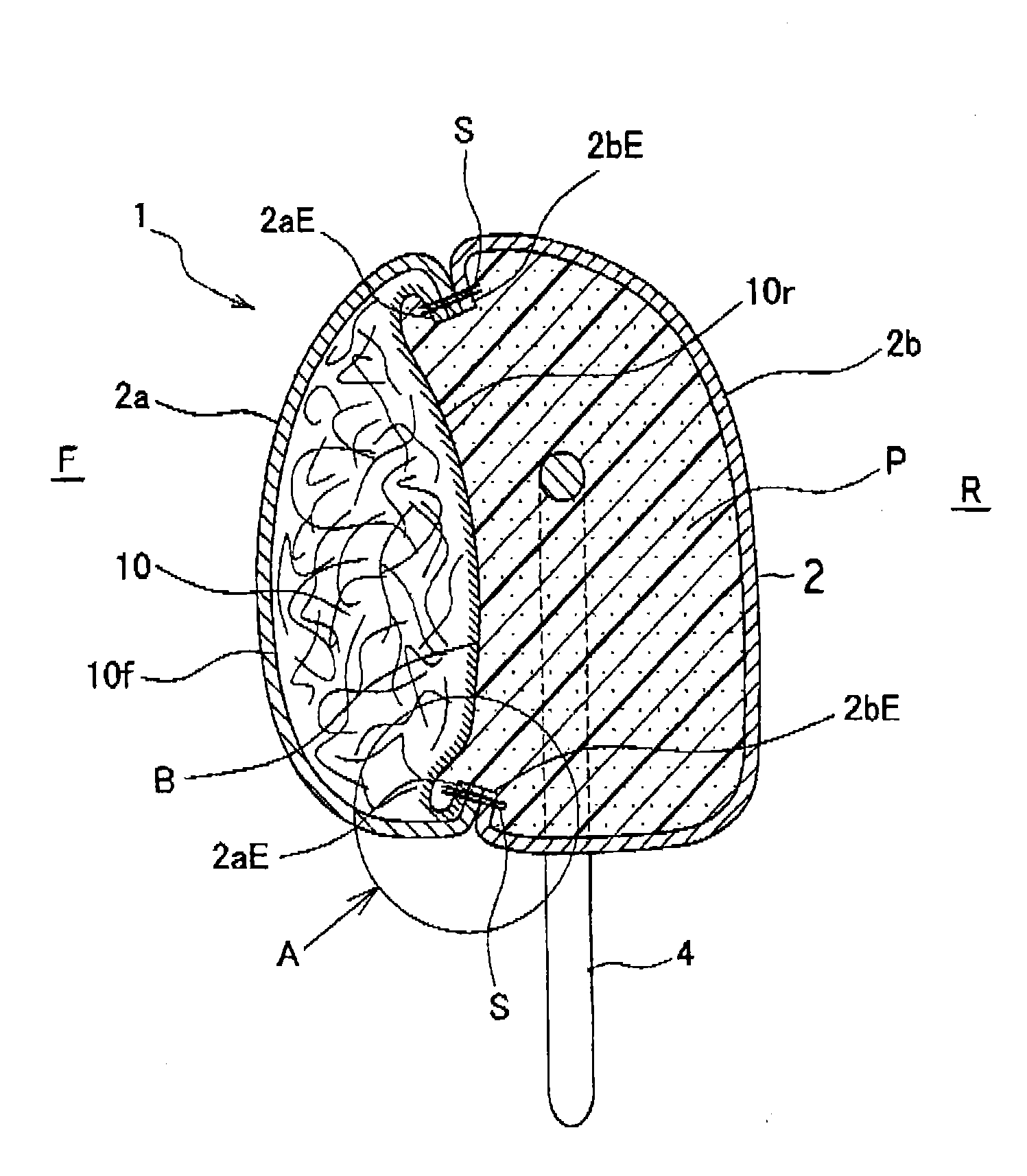
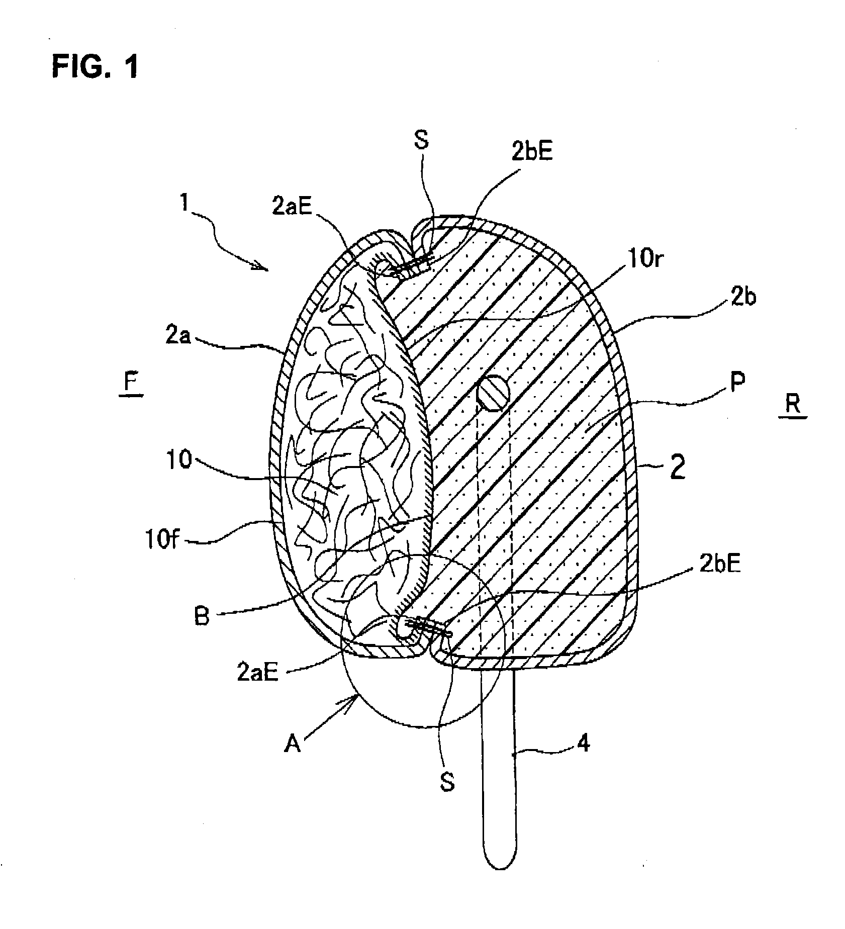
[0020]As shown in FIG. 1, a headrest 1 is comprised of: a three-dimensional trim cover element 2 formed in a three-dimensional bag-like shape by means of sewing; a foam padding P provided in the trim cover element 2, wherein the foam padding has been formed by injecting and curing a liquid foaming agent (e.g. liquid urethane foaming agent) in the trim cover element; and a stay 4 fixed to a headrest frame provided in the foam padding P. Therefore, the headrest 1 is what can be described as a foam product integral with a trim cover element.

[0021]The trim cover element 2 includes: a front surface region 2a facing a side (a forward side F) where a passenger's head is to be received; and a rear surface region 2b facing a rearward side R. As will be described later, a peripheral end portion 2aE of the front surface r...


PUM


Abstract

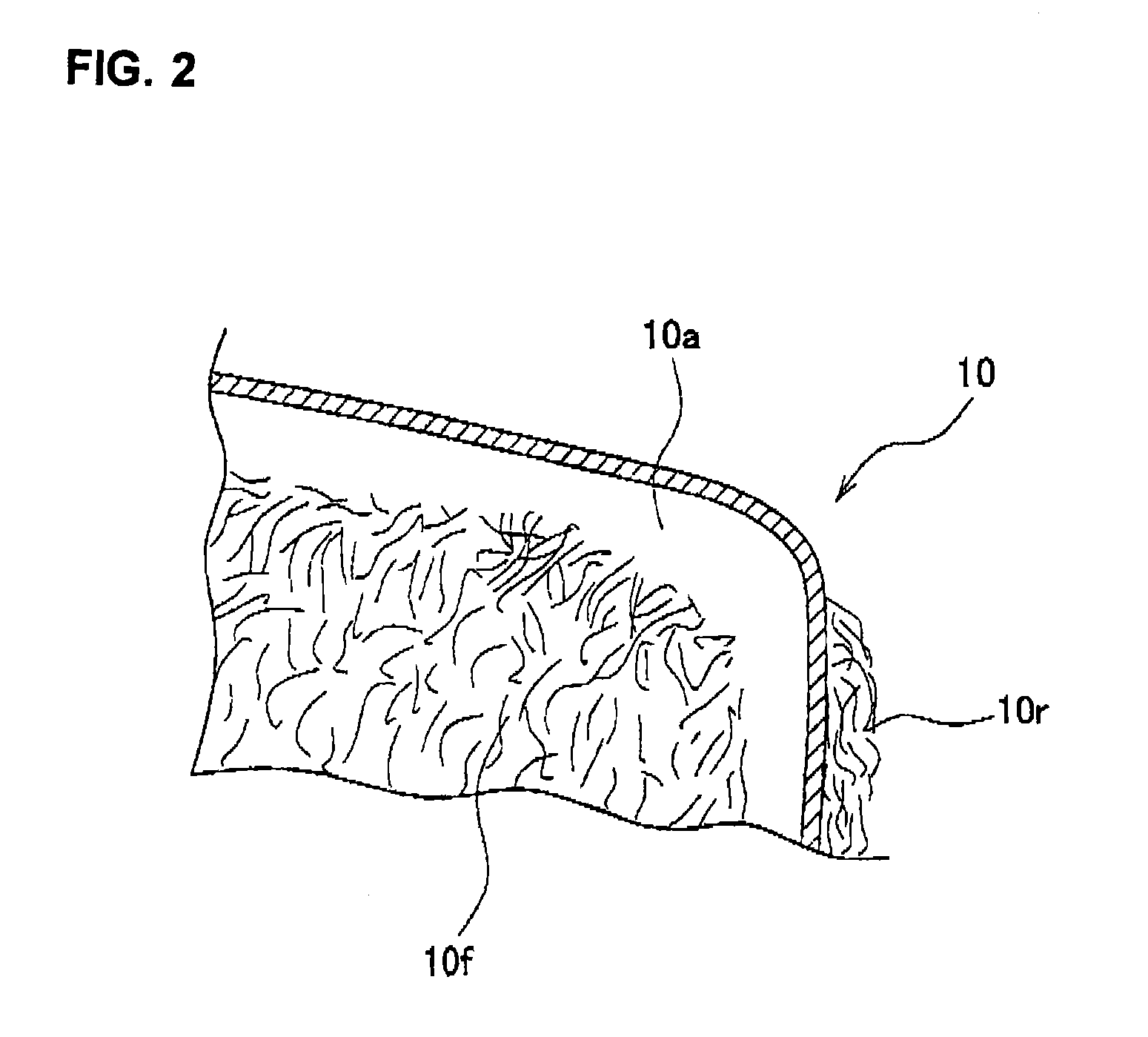
A headrest including: a trim cover element formed in a three-dimensional bag-like configuration, a fiber assembly; and a foam padding. The fiber assembly and foam padding are both provided within the trim cover element in such a manner that the fiber assembly is secured to and positioned on a front surface side of the trim cover element, whereas the foam padding is positioned on a rear surface side of the fiber assembly. The foam padding has been created by a foaming process so as to be integral with the trim cover element and fiber assembly.

Description

TECHNICAL FIELD[0001]The present invention relates to a headrest for use with an automotive seat.BACKGROUND ART[0002]Japanese Patent No. 4490213 discloses a conventional technology in this headrest field. A headrest described in this prior art includes a foam padding and a stay supported on a seat, the stay being at its upper portion embedded in the foam padding. This stay is formed by: a pair of leg portions which are exposed from the foam padding and extend in a predetermined spaced-apart and parallel relation with each other; and an inverted-U-shaped load receiving portion defined between those two leg portions at an upper region of the stay. The foam padding consists of one foam padding element having a normal-repulsive elasticity and another foam padding element having a low-repulsive elasticity. A process for forming this kind of headrest entails: providing a three-dimensional trim cover element; attaching a low-repulsive foam padding element to a forwardly-facing inner surfac...

Claims


Application Information

Patent Timeline
IPC IPC(8): B60N2/48B60N2/58
CPCB60N2/48B60N2/5883B60N2/5875B60N2/5891B60N2/7017B60N2/80B60N2/58
Inventor MIYATA, KEIYOSHIKAWA, JUNPEI
Owner TACHI S CO LTD
Learn More