Method of manufacturing resin molded product

Inactive Publication Date: 2007-08-23
YOSHIDA KOGYO KK
View PDF4 Cites 20 Cited by
  • Summary
  • Abstract
  • Description
  • Claims
  • Application Information

AI Technical Summary

Benefits of technology

[0010] An object of the present invention is to provide a manufacturing method for ob

Problems solved by technology

However, if a heavy construction such as the decorating sheet carrying unit is disposed on the side of the movable mold which is rotated as described above, a large rotary driving force is needed.
Although it can be considered to use a small decorating sheet carrying unit as described in the patent document in order to solve this problem, the decorating sheet itself becomes small

Method used


Image

  • Method of manufacturing resin molded product
  • Method of manufacturing resin molded product
  • Method of manufacturing resin molded product

Examples


first embodiment

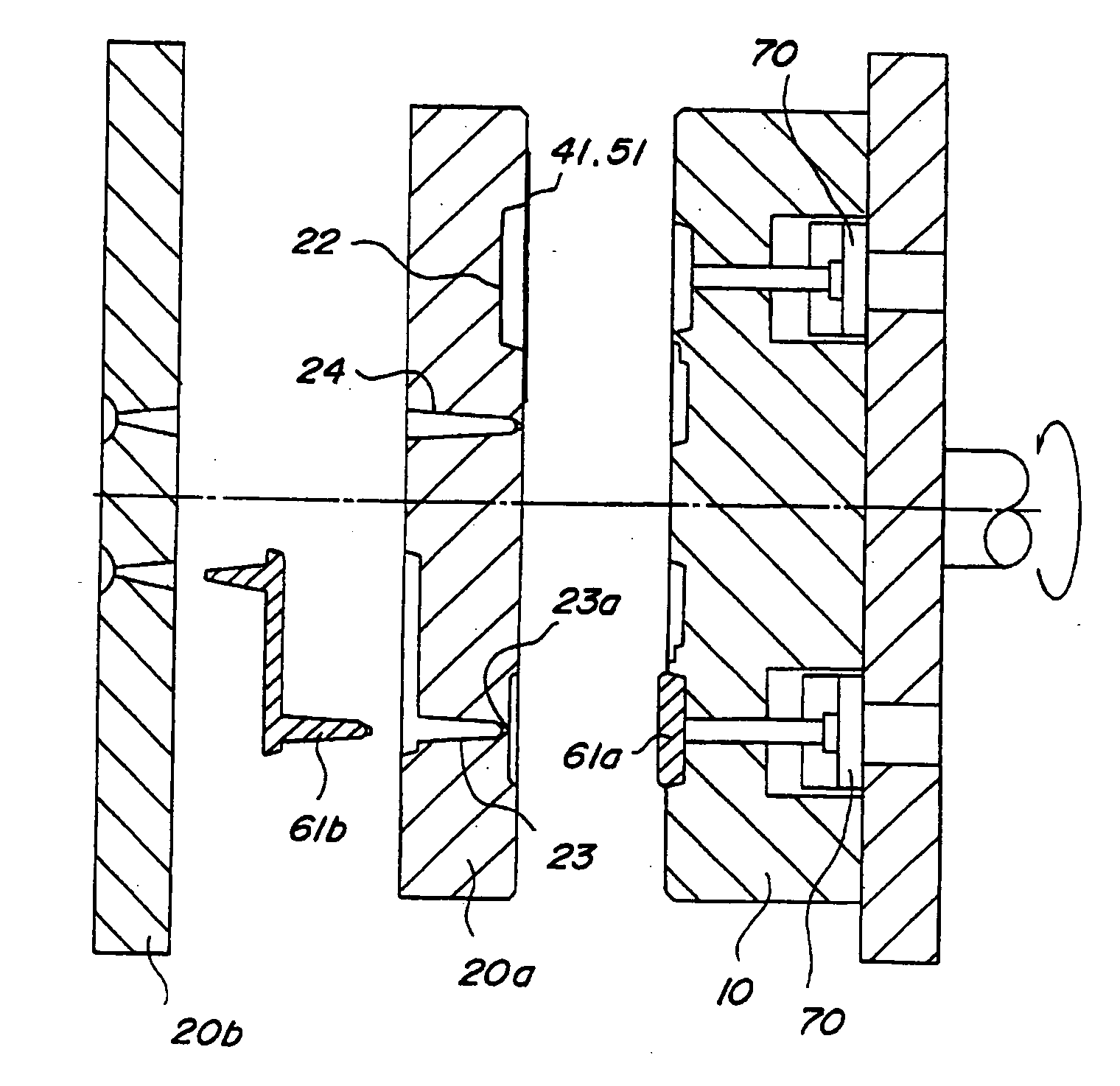
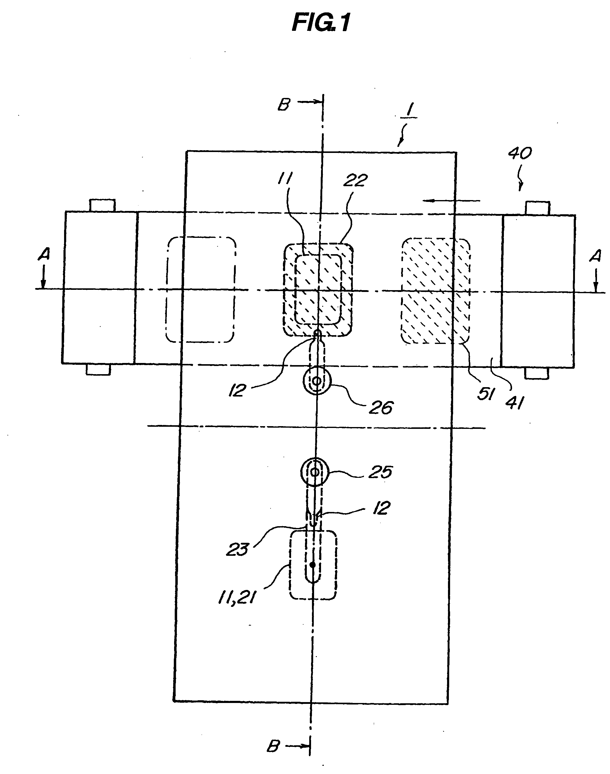
[0035] The embodiment of the present invention will be described with reference to the accompanying drawings. (Manufacturing apparatus) The structure of the manufacturing apparatus will be described with reference to FIGS. 1 to 3B. FIG. 1 is a front view of the manufacturing apparatus. FIG. 2 is a sectional view of the manufacturing apparatus as seen from above (sectional view taken along a line A-A of FIG. 1). FIGS. 3A and 3B are sectional views of the manufacturing apparatus as seen from sideway (sectional view taken along a line B-B of FIG. 1).

[0036] As shown in FIGS. 1 to 3B, the manufacturing apparatus 1 for resin molded product includes a movable mold 10 each having two movable side cavities 11 and side gates 12 and a fixed mold 20 having a fixed side primary cavity 21 and a fixed side secondary cavity 22. The fixed mold 20 includes a forming mold 20a having the cavities 21, 22 and resin introduction paths 23, 24 and a pouring mold 20b having resin pouring ports 25, 26.

[0037...

second embodiment

[0063] Although the configuration of the gate to the cavity in the secondary side is of the side gate 12 in the first embodiment, that gate is not limited to this example. For example, it is permissible to adopt a submarine gate 112 by squeezing part of the aforementioned side gate 12. In this case, if the movable mold 10 and the fixed mold 20 are separated, the secondary resin is separated at the squeezed portion. Consequently, step of removing a runner after the secondary resin molded product is obtained can be omitted thereby making the manufacturing process more effective.

[0064] Although in the first embodiment, the two cavities 21, 22 and the two introduction paths 23, 24 are constructed integrally in one fixed mold 20, this embodiment is not restricted thereto. For example, as shown in FIG. 8, a fixed mold 120 to be fixed to a base 102 may be constituted of a plurality of templates. In this embodiment, the fixed mold 120 is constituted of two templates of a fixed side primary...

third embodiment

[0067] The embodiment of the present invention will be described with reference to the accompanying drawings.

(Manufacturing Apparatus)

[0068] The structure of the manufacturing apparatus will be described with reference to FIGS. 9 to 11B. FIG. 9 is a front view of the manufacturing apparatus, FIG. 10 is a sectional view of the manufacturing apparatus as seen from above (sectional view taken along a line A-A of FIG. 9) and FIGS. 11A and 11B are a sectional view of the manufacturing apparatus as seen from sideway (sectional view taken along a line B-B of FIG. 9).

[0069] As shown in FIGS. 9 to 11B, the manufacturing apparatus 201 for resin molded product includes a movable mold 210 having two cavities 211 and gates 212, 213 and a fixed mold 220 having cavities 221, 222.

[0070] As shown in FIG. 10, the manufacturing apparatus 201 includes a primary decorating film carrying means 241 and a secondary decorating film carrying means 242 provided integrally with the fixed mold 220. Further...


PUM


Abstract

A resin molded product manufacturing apparatus includes, a movable mold having a pair of movable side cavity and side gate formed symmetrically with respect to an axis; a fixed mold having a fixed side primary cavity and a fixed side secondary cavity; and primary and secondary resin injecting units and a decorating film carrying unit disposed on the fixed mold. The manufacturing method includes closing the molds and injecting primary resin into the fixed side primary cavity to form a primary resin molded product; opening the molds and rotating the movable mold around the rotation axis symmetrically with respect to the axis; and, with a decorating film placed on the fixed side secondary cavity, closing the molds and injecting secondary resin from the side gate between the movable side cavity and the fixed side secondary cavity to form a decorated secondary resin molded product.

Description

CROSS-REFERENCE TO RELATED APPLICATION [0001] This application claims the benefit of priority from the prior Japanese Patent Application Nos. 2006-42374 and 2006-42375, the entire contents of which are incorporated by reference herein. BACKGROUND OF THE INVENTION [0002] 1. Field of the Invention [0003] The present invention relates to a method of manufacturing resin molded product for double molding by injecting two kinds of synthetic resins each having a different material and color tone. [0004] 2. Description of the Related Art [0005] Conventionally, double molding has been performed by injecting two kinds of synthetic resins each having a different material and color tone. (see, for example, Japanese Patent Application Laid-Open Nos. 9-183139, 9-183140, 9-183141 and 9-183142). [0006] According to these conventional technologies, an injection molding machine is disposed on the side of a fixed mold and a carrying unit for a decorating sheet is disposed integrally on the side of a m...

Claims


Application Information

Patent Timeline
IPC IPC(8): B29C45/00
CPCB29C45/062B29C45/14008B29C2045/1673B29C45/1671B29C45/2708B29C45/162
Inventor SHIMOYAMA, TADAYOSHIARAKAWA, YUKIYASUIDESHITA, YUJIYUHARA, YUKITOMO
Owner YOSHIDA KOGYO KK
Why Eureka
Try Eureka