Sensor device for vehicles

a technology for sensors and vehicles, applied in the direction of instruments, specific gravity measurement, furnaces, etc., can solve the problems of large size, large signal characteristic of ultrasonic sensors to vary to different and undetectable extents, and achieve minimal detuning, excellent visual adaptation, and optimal functioning of ultrasonic sensors

Active Publication Date: 2007-08-23
ROBERT BOSCH GMBH
View PDF12 Cites 24 Cited by
  • Summary
  • Abstract
  • Description
  • Claims
  • Application Information

AI Technical Summary

Benefits of technology

[0010] In contrast to known specific embodiments, the sensor device of the present invention has the advantage of offering not only an excellent visual adaptation to chrome-colored or chrome-coated external vehicle components, but of causing only an extremely minimal detuning of the ultrasonic sensor at the same time. An optimal functioning of the ultrasonic sensor is able to be achieved in a cost-effective manner using an especially simple design and with particularly low expenditure in terms of manufacturing technology.
[0012] The use of chrome foil to cover the ultrasonic sensor results in a very satisfactory optical adaptation to chrome-colored and chrome-plated external vehicle components. Surprisingly, the problem of sensor detuning, i.e., the raising of the resonant frequency of the ultrasonic sensor, does not arise when chrome foil is used. Overall, the chrome foil is thin enough not to change the mechanical properties of the ultrasonic sensor to any significant degree. It is true that the mechanical properties of the sensor are slightly modified, in particular the natural oscillation frequency of the housing or the diaphragm lowered and the transmission frequency of the sensor lowered as a result; also, the post-oscillation response is affected to a negligible degree, since the chrome foil tends to have a damping effect. However, the mentioned changes in the mechanical properties are low compared to the machining / covering by chrome plating; above all, they are predictable and therefore more easily remedied.
[0013] Although the foil according to the present invention is primarily intended for visual adaptation to the environment of the chrome-colored installation location, it may simultaneously provide protection against corrosion as well.
[0016] For instance, a preferred development of the present invention may be achieved in that an edge region is adjacent to the planar surface of the sensor cover, the edge region being able to be brought into contact with an upper jacket section of a sensor cup or housing of the ultrasonic sensor. In this case the foil sits on the sensor cup like a lid. This refinement, in particular, also provides improved corrosion protection since the edge of the foil makes contact only with the jacket surface of the sensor cup and not already with the region of its outer edge surrounding the end face.
[0019] An especially small change in the mechanical properties of the ultrasonic sensor may be achieved by designing the sensor cover without metal and making it exclusively from plastic.
[0020] Furthermore, minimal changes in the mechanical properties of the ultrasonic sensor may be achieved if the sensor cover has a thickness of between 10 μm and 600 μm, preferably between 50 μm and 200 μm. Nevertheless, thicker foils may be used as well.

Problems solved by technology

However, this procedure has the serious disadvantage of having a highly adverse effect on the mechanical properties of the outer oscillatory diaphragm of the ultrasonic sensor inasmuch as it results in a changed E module and changed damping.
There is the particular problem that the layer thickness of the primer coat and chrome layer may vary, which causes the signal characteristic of the ultrasonic sensor to vary to different and undesired extents as well.
Even if the variation of the layer thickness is able to be kept relatively minimal, it nevertheless leads to relatively large and, above all, unpredictable deviations due to the very narrow frequency band in which the sensor element is operating.

Method used


Image

  • Sensor device for vehicles
  • Sensor device for vehicles
  • Sensor device for vehicles

Examples


Embodiment Construction

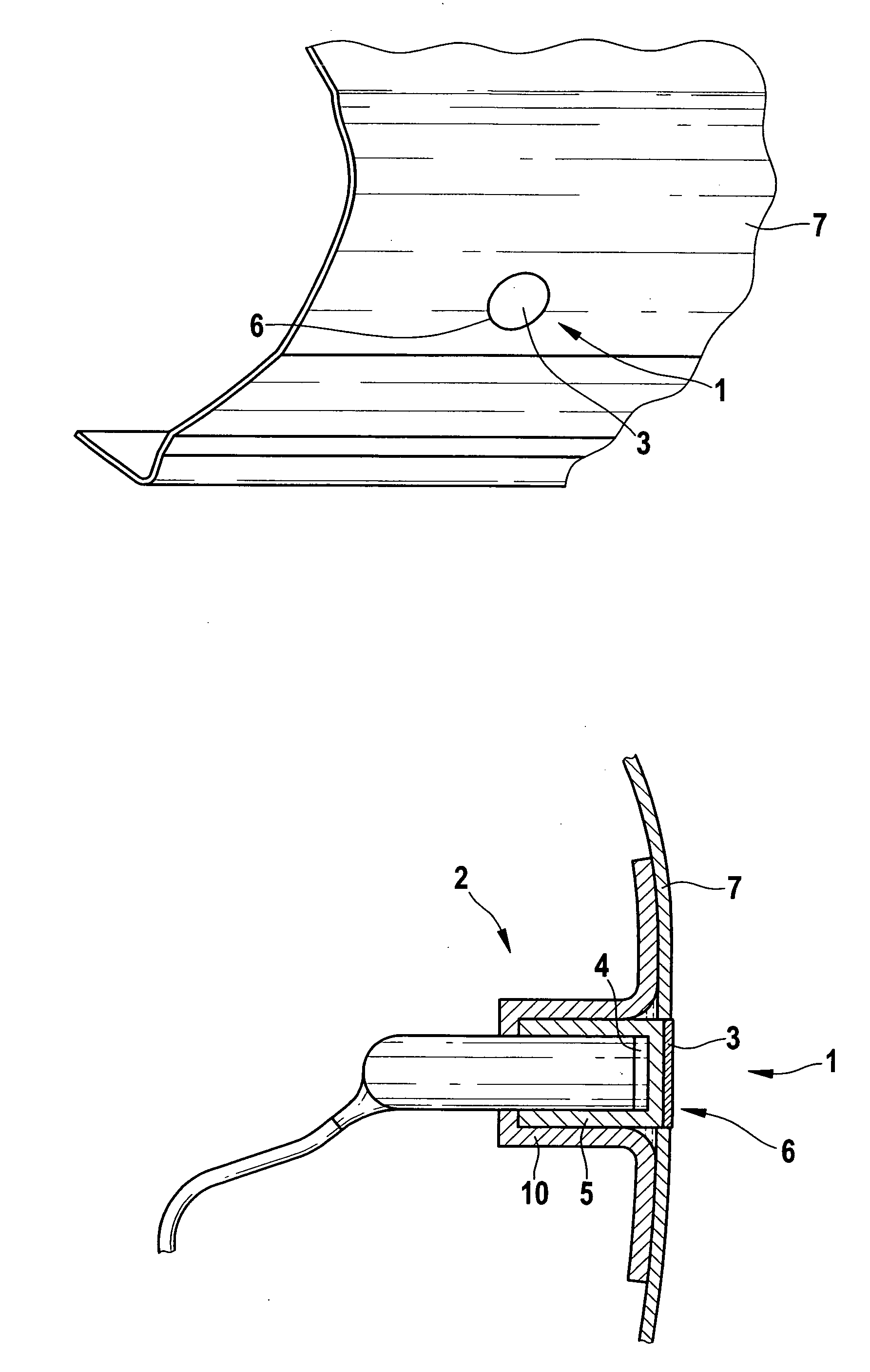
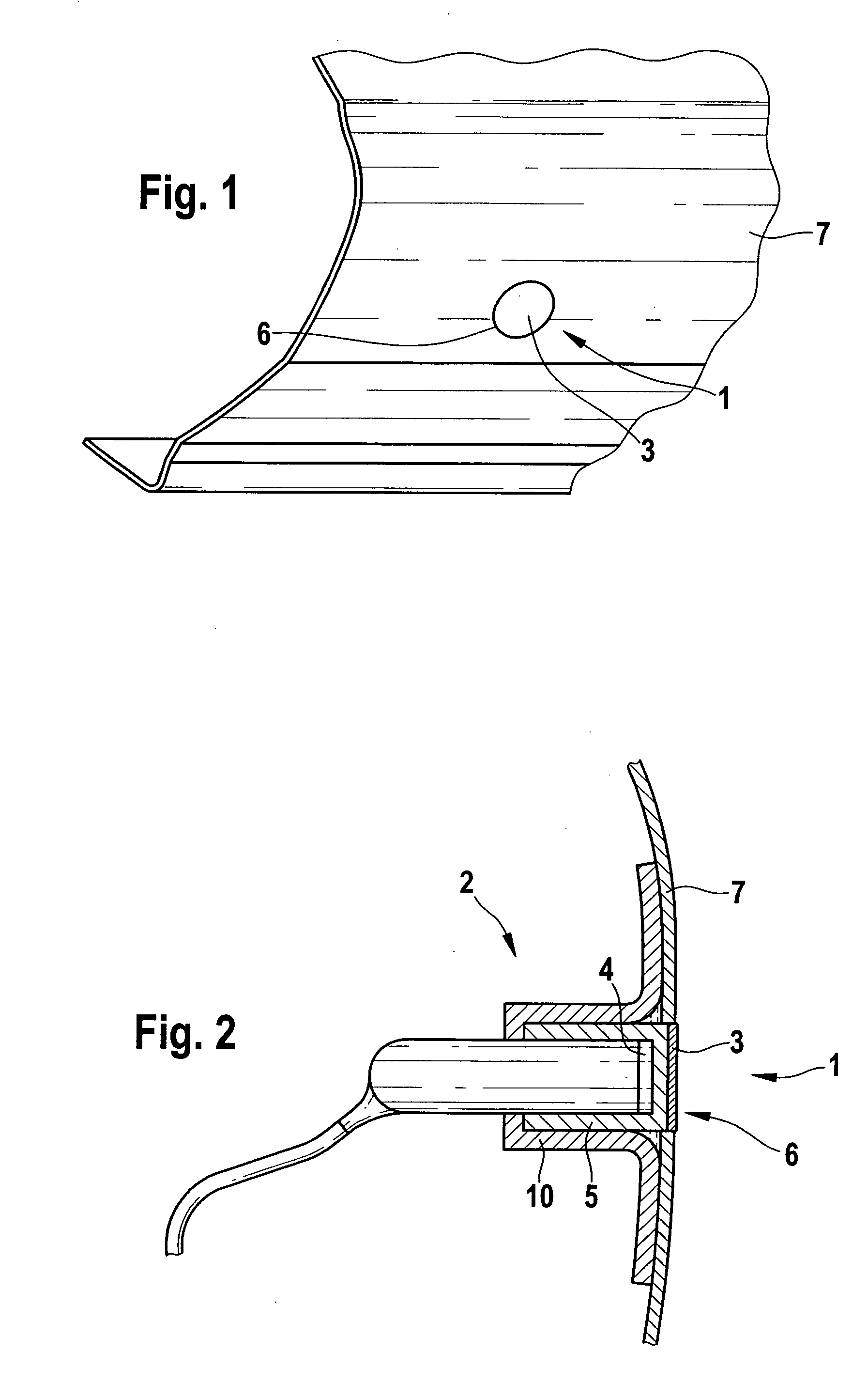
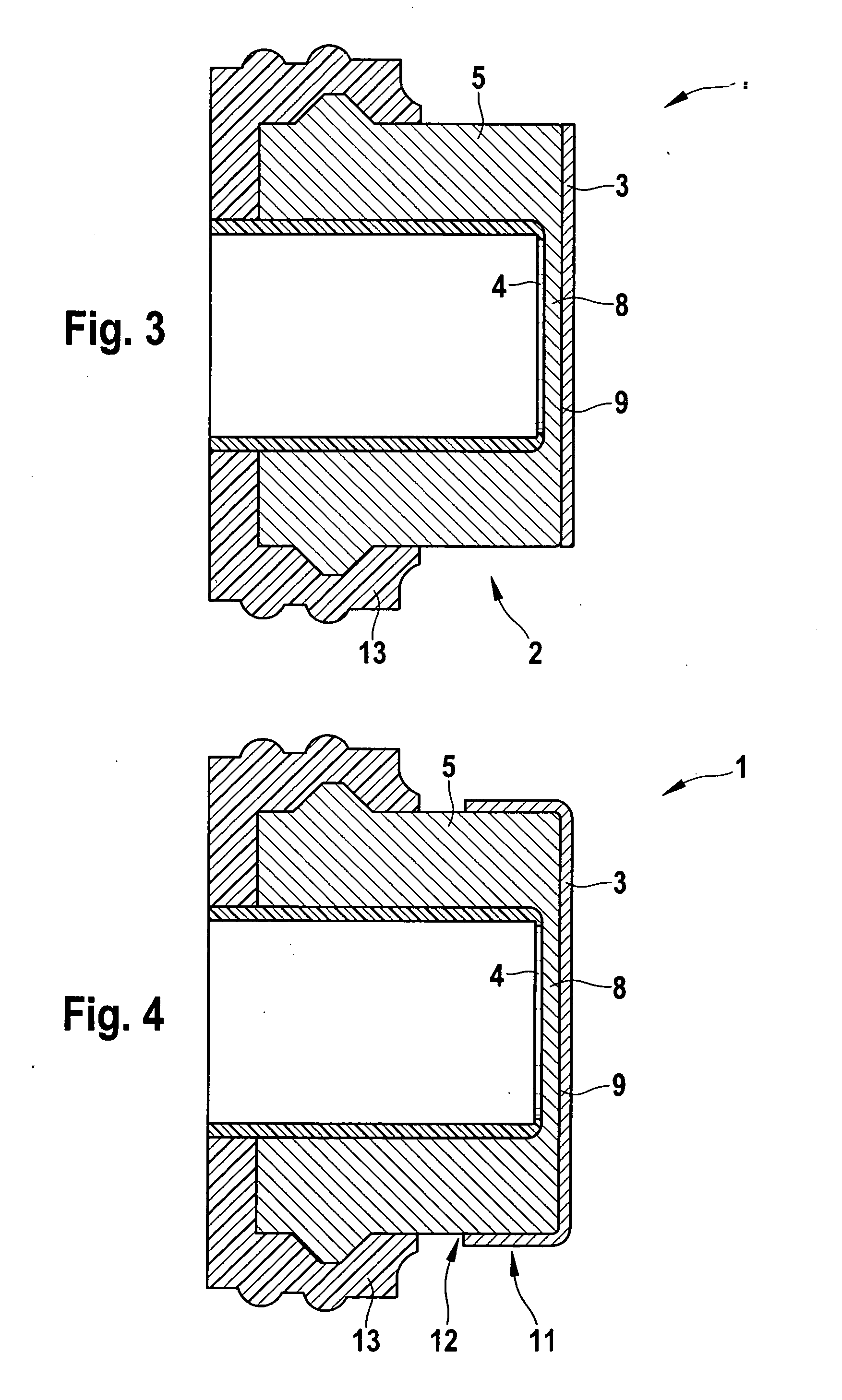
[0028] Sensor device 1 shown in the figures is essentially made up of an ultrasonic sensor 2 and a sensor cover 3 which is bonded thereto and formed by a chrome foil. Ultrasonic sensor 2 itself includes an oscillatory sensor element 4 in the form of a sensor diaphragm, for instance, which is supported inside a cup-shaped housing 5 of ultrasonic sensor 2.

[0029] Ultrasonic sensor 2 is accommodated in a bore hole 6 of an external vehicle component 7 in the form of a shock absorber, in such a way that front end wall 8 of housing 5 having a thickness of approximately 0.6 mm is situated completely inside bore hole 5. The outside surface of end face 9 of housing 5 is flush with the opening cross section of bore hole 6.

[0030] The chrome foil as sensor cover 3 is bonded directly to end face 9. Its form and size are adapted to end face 9. In particular, chrome foil 3 thus does not project beyond the opening cross section formed by bore hole 6 and completely covers ultrasonic sensor 2 on the...


PUM


Abstract

A sensor device includes an ultrasonic sensor and a sensor cover in the form of a foil, the ultrasonic sensor having an oscillatory sensor element, which is affixed inside a housing, having an end face, of the ultrasonic sensor, the ultrasonic sensor being able to be accommodated in a recess or bore hole of an external vehicle component, and the sensor element and the housing being able to be covered by the sensor cover on the outside, the sensor cover being mountable directly on the ultrasonic sensor and forming an at least essentially planar surface whose outline is adapted to the outline of the end face of the housing and coincides in an essentially flush manner with the end face of the housing of the ultrasonic sensor, and the sensor cover reflecting light having a color spectrum in the range of chrome color and a reflection capacity in the range of polished chrome.

Description

FIELD OF THE INVENTION [0001] The present invention relates to a sensor device for vehicles, to an installation method suitable for such, as well as to a sensor cover for a sensor device of this type. The sensor device includes an ultrasonic sensor and a sensor cover in the form of a foil, and the ultrasonic sensor is able to be accommodated in a recess or bore hole of an external vehicle component; it has an oscillatory sensor element, which is supported inside a housing of the ultrasonic sensor, and a sensor cover may cover the sensor element and the housing on the outside. BACKGROUND INFORMATION [0002] Such sensor devices are used especially in motor vehicles within the framework of driver assistance systems known as park distance control (PDC), in order to assist the driver during maneuvering or parking of the motor vehicle. These PDC systems operate with the aid of ultrasonic distance-measuring devices, which are normally mounted only in the rear section or in the rear section ...

Claims


Application Information

Patent Timeline
Patent Type & Authority Applications(United States)
IPC IPC(8): B60Q1/00G08G1/14G08B23/00
CPCG01S7/521B60R19/483
Inventor SCHAAF, GUNTHERJANKE, NILS
Owner ROBERT BOSCH GMBH
Why Eureka
Try Eureka