Source driver circuit for controlling slew rate according to frame frequency and method of controlling slew rate according to frame frequency in the source driver circuit

a source driver circuit and frame frequency technology, applied in the direction of heating types, instruments, separation processes, etc., can solve the problem of increasing the power consumption of tft_lcd b>100/b>

Inactive Publication Date: 2007-08-23
SAMSUNG ELECTRONICS CO LTD
View PDF8 Cites 16 Cited by
  • Summary
  • Abstract
  • Description
  • Claims
  • Application Information

AI Technical Summary

Benefits of technology

[0023]The source driver circuit can further include a frequency comparator. The frequency comparator outputs a frequency difference between the actual frame frequency and a reference frame frequency. The frequency-current converting unit outputs a control current that is changed in amount according to the frequency difference. The bias current outputting unit sums a reference bias current with the control current and outputs the summed result as the bias current.
[0024]The bias current outputting unit sums the reference bias current with the control current and outputs the summed result as the bias current if the actual frame frequency is greater than the reference frame frequency. If the actual frame frequency is less than the reference frame frequency the bias current outputting unit subtracts the control current from the reference bias current and outputs the subtracted result as the bias current.
[0025]According to an exemplary embodiment of the present invention, there is provided a method for controlling a slew rate in a source driver circuit, including; outputting a control curre

Problems solved by technology

Accordingly, a problem exists that power

Method used


Image

  • Source driver circuit for controlling slew rate according to frame frequency and method of controlling slew rate according to frame frequency in the source driver circuit
  • Source driver circuit for controlling slew rate according to frame frequency and method of controlling slew rate according to frame frequency in the source driver circuit
  • Source driver circuit for controlling slew rate according to frame frequency and method of controlling slew rate according to frame frequency in the source driver circuit

Examples


Embodiment Construction

[0033]The attached drawings for illustrating exemplary embodiments of the present invention are referred to in order to gain a sufficient understanding of the present invention, the merits thereof, and the objectives accomplished by the implementation of the present invention.

[0034]Hereinafter, the present invention will be described in detail by explaining exemplary embodiments of the present invention with reference to the attached drawings. Like reference numerals in the drawings denote like elements.

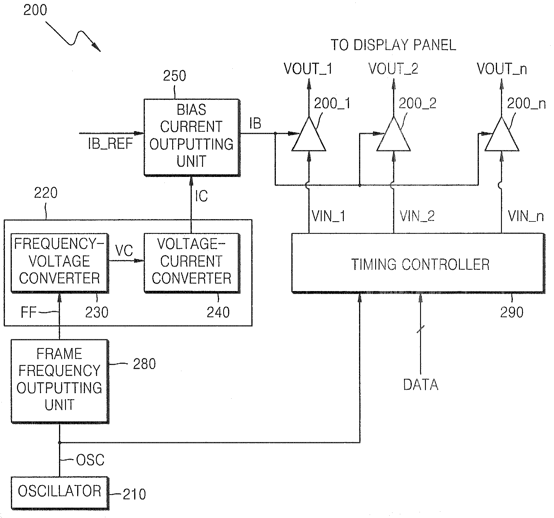
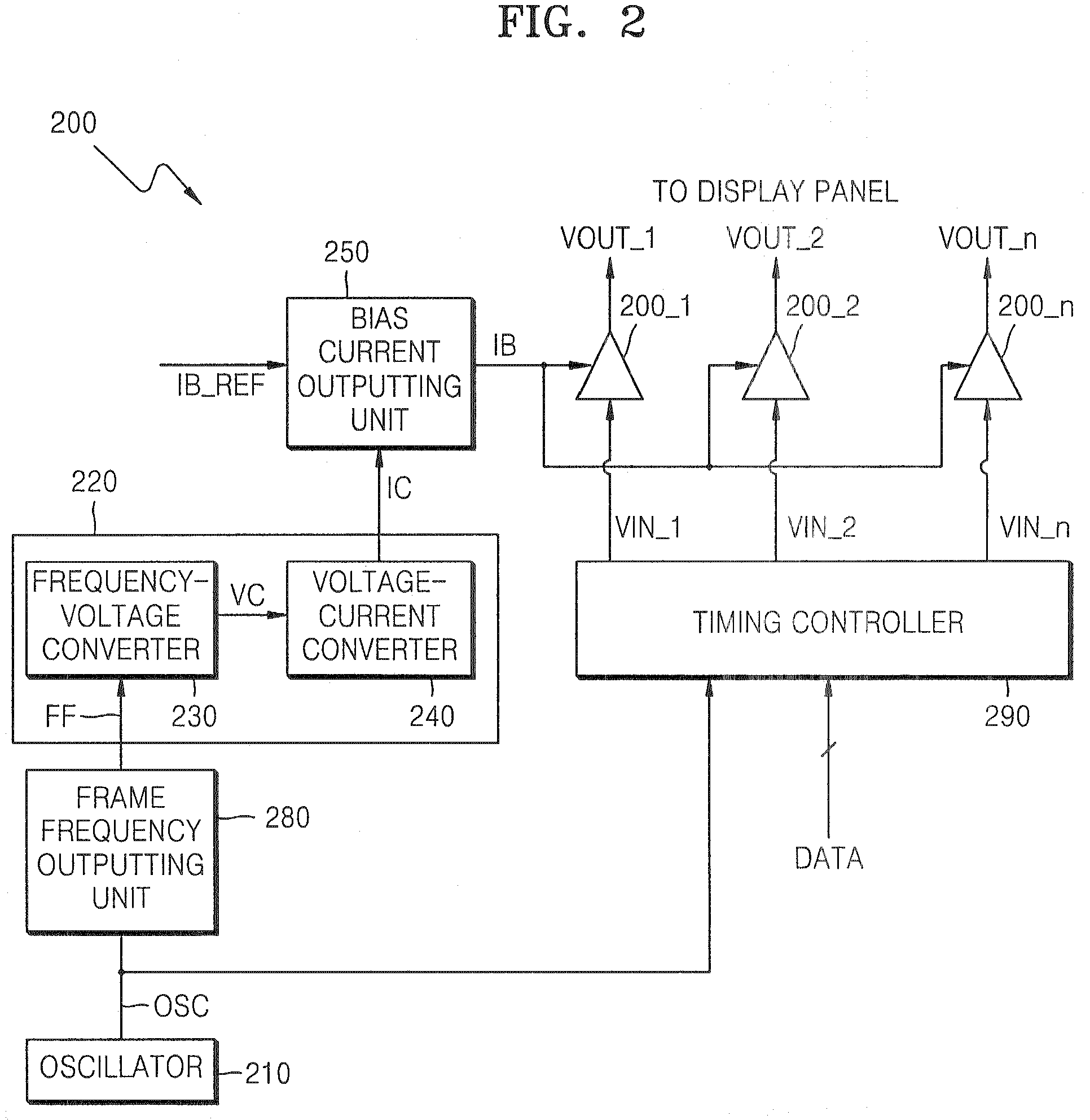
[0035]FIG. 2 is a block diagram of a source driver circuit 200 in which a slew rate is controlled according to a frame frequency, according to an exemplary embodiment of the present invention.

[0036]Referring to FIG. 2, the source driver circuit 200 includes a plurality of driver amplifiers 200_1 through 200—n, a frequency-current converting unit 220, and a bias current outputting unit 250. The driver amplifiers 200_1 through 200—n receive input voltages VIN_1 through VIN—n and genera...


PUM

PropertyMeasurementUnit
Currentaaaaaaaaaa
Frequencyaaaaaaaaaa

Abstract

A source driver circuit in which a slow rate is adjusted according to a frame frequency and a method for adjusting a slew rate according to a frame frequency in the source driver circuit, wherein the source driver circuit includes a plurality of driver amplifiers, a frequency-current converting unit, and a bias current outputting unit. The driver amplifiers receive input voltages, generate output voltages, and adjust slew rates of the output voltages according to an amount of a bias current. The frequency-current converting unit receives a frame frequency and outputs a control current having an amount of the control current adjusted according to the frame frequency. The bias current outputting unit adjusts an amount of a bias current according to the amount of the control current and outputs the adjusted bias current to the driver amplifiers. Therefore, in the source driver circuit and the method for controlling the slew rate in the source driver circuit, by adjusting a slew rate of an output voltage of a driver amplifier according to a frame frequency, it is possible to reduce power consumption while ensuring a time required for displaying gradation data.

Description

CROSS-REFERENCE TO RELATED PATENT APPLICATION[0001]This application claims the benefit of Korean Patent Application No. 10-2006-0017307 filed on Feb. 22 2006, in the Korean Intellectual Property Office, the disclosure of which is incorporated herein in its entirety by reference.BACKGROUND OF THE INVENTION[0002]1. Technical Field[0003]The present disclosure relates to a source driver circuit of a liquid crystal display apparatus and a method of controlling a slew rate in the source driver circuit and, more particularly, to a source driver circuit for controlling a slew rate according to a frame frequency and a method of controlling a slew rate according to a frame frequency in the source driver circuit.[0004]2. Discussion of Related Art[0005]FIG. 1 is a view schematically showing a known thin-film transistor liquid crystal display (TFT-LCD) 100.[0006]Referring to FIG. 1, the TFT-LCD 100 generally includes a display panel 110, a gate driver circuit 120, and a source driver circuit 200...

Claims


Application Information

Patent Timeline
IPC IPC(8): G09G3/36
CPCG09G3/3648G09G2340/0435G09G2320/0252G09G3/3688B01D35/28F16K31/20F24D3/122F24D19/1015
Inventor KWON, HYEOK-CHUL
Owner SAMSUNG ELECTRONICS CO LTD
Why Eureka
Try Eureka