Program managed design for complex construction projects

a technology for managing design and construction projects, applied in the field of project management tools, can solve the problems that the construction of complex building projects typically requires an immense effort in coordinating a multitude of skilled professionals, and achieve the effect of time, cost and content control over complex building design projects

Inactive Publication Date: 2007-08-23
GANNON TECH GROUP
View PDF12 Cites 48 Cited by
  • Summary
  • Abstract
  • Description
  • Claims
  • Application Information

AI Technical Summary

Benefits of technology

The patent describes methods for managing complicated building designs with programmed controls that save money and improve efficiency.

Problems solved by technology

This patent describes a method called Programmed Management Design (PMD) that helps organize and manage large building designs involving multiple teams of experts. The problem this technology solves is how to efficiently handle the vast amount of information needed for creating detailed blueprints and managing costs associated with constructing buildings. By utilizing a computerized system based on graphics and programming principles, PMD simplifies the way we plan and build things, resulting in better outcomes and more efficient use of resources.

Method used


Image

  • Program managed design for complex construction projects
  • Program managed design for complex construction projects
  • Program managed design for complex construction projects

Examples


Embodiment Construction

.”

BRIEF DESCRIPTION OF THE DRAWINGS

[0013] For a more complete understanding of the principles disclosed herein, and the advantages thereof, reference is now made to the following descriptions taken in conjunction with the accompanying drawings, in which:

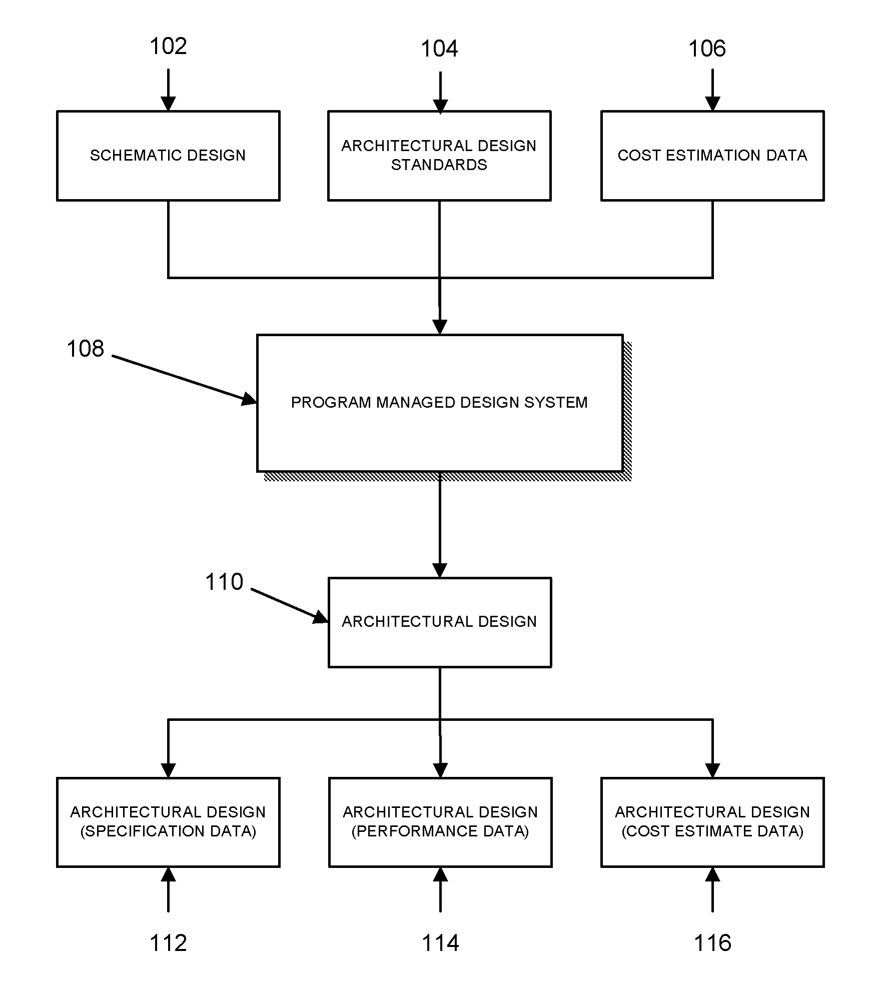
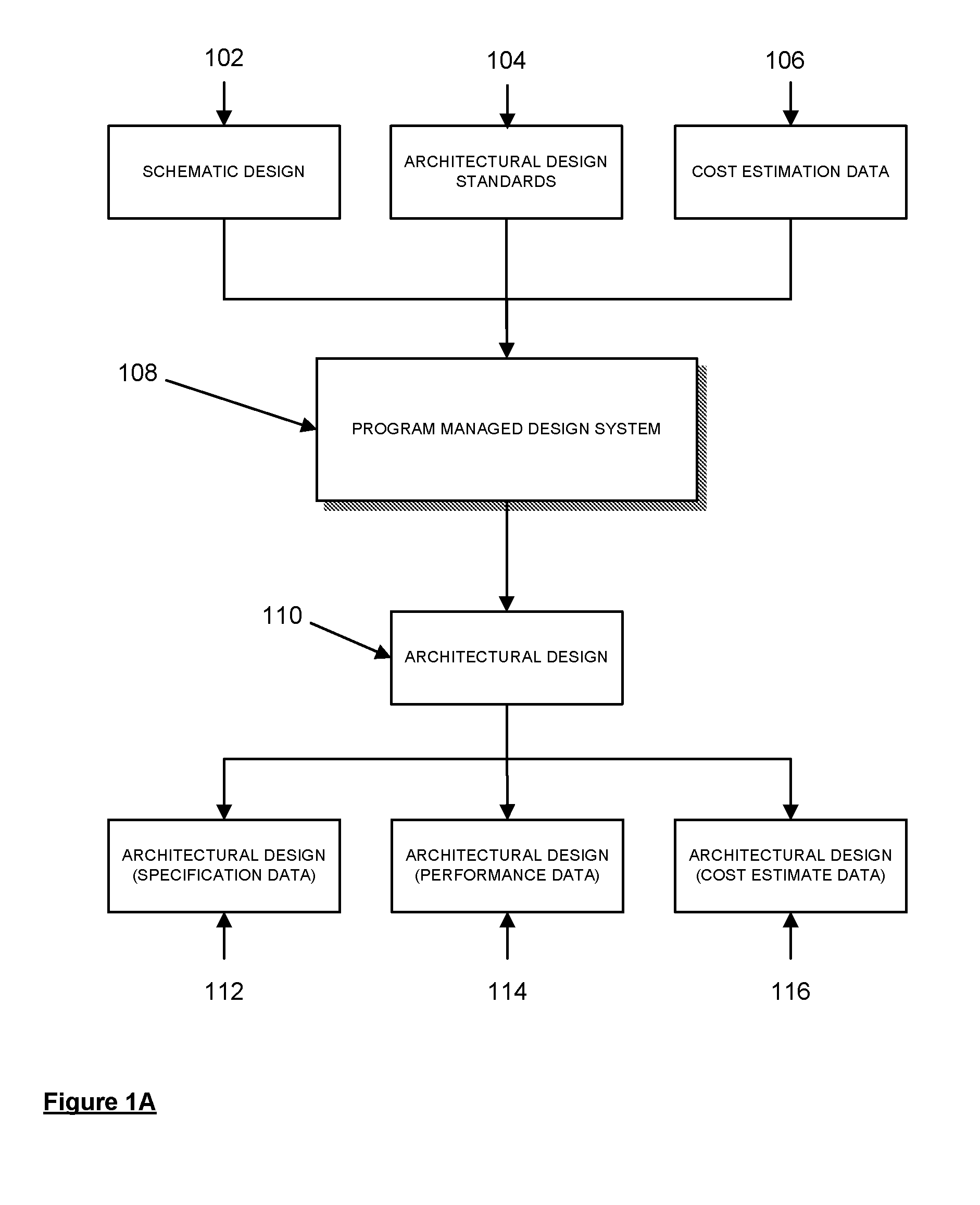
[0014]FIG. 1A is an illustration of a flowchart depicting the range of data inputs that are fed into a PMD System and the data outputs that result, in accordance with one embodiment.

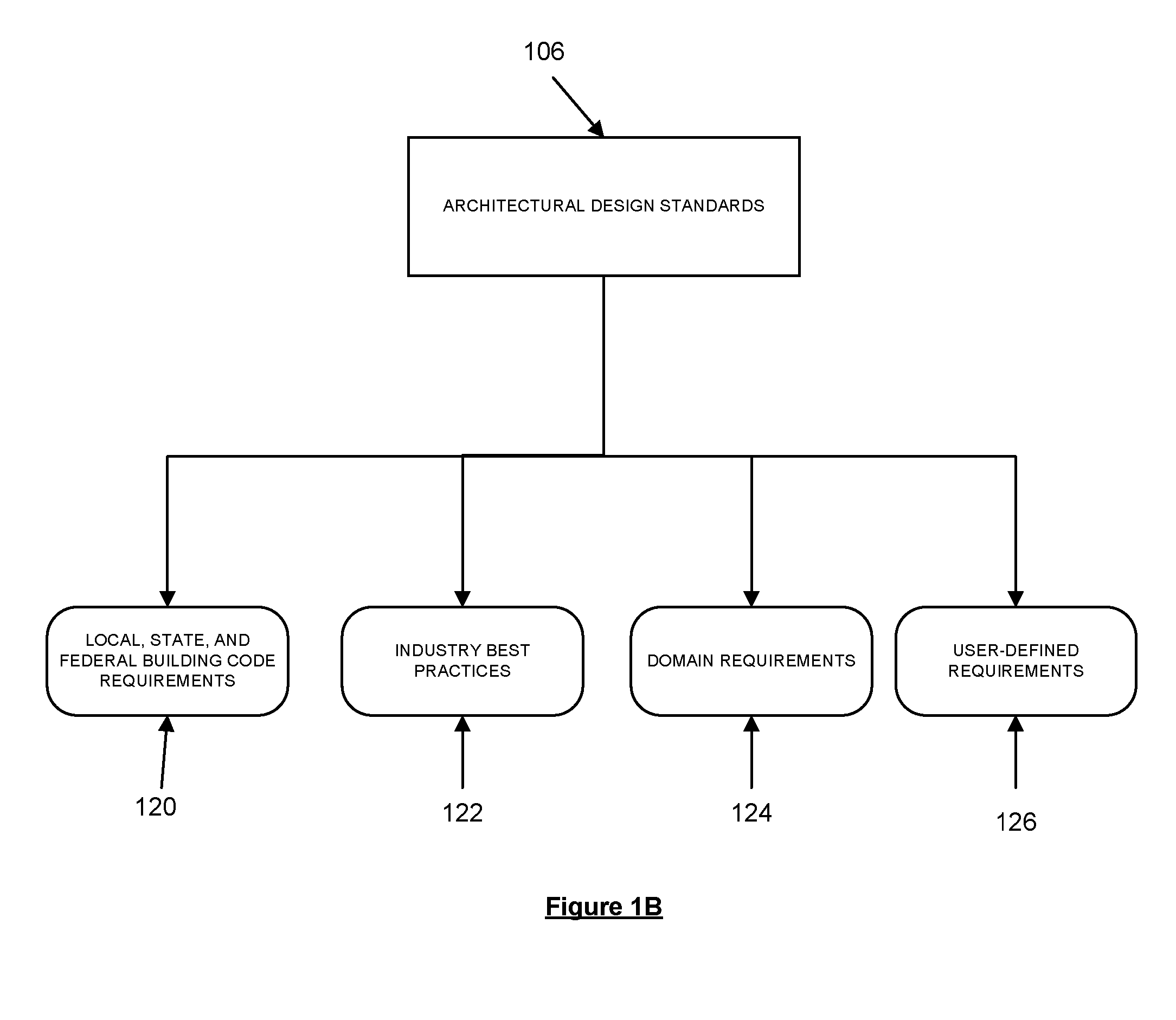
[0015]FIG. 1B is an illustration of the various sources of data that the Architectural Design Standards draws from, in accordance with one embodiment.

[0016]FIG. 2 is an illustration of how two functional areas demarcated on a schematic map are graphically tagged, in accordance with one embodiment.

[0017]FIG. 3A is an illustration of a schematic drawing with multiple tagged spaces, in accordance with one embodiment.

[0018]FIG. 3B is an illustration of a schematic drawing once triangulation has occurred, in accordance with one embodiment.

[0019]FIG. 3C ...


PUM


Abstract

A method for generating architectural design requirements for a building structure is disclosed. A schematic drawing file of the building structure is loaded. The building type for the building structure is designated. A topology mask identifying the functional zones demarcated by the schematic drawing is created over the schematic drawing. Architectural design standards that are specific to the building type designated are applied to each of the identified functional zones to generate the architectural design requirements for the building structure. The architectural design standards being stored in a relational database.

Description


Claims


Application Information

Patent Timeline
Owner GANNON TECH GROUP
Why Eureka
Try Eureka