
Systems and methods for high speed variable printing

a variable printing and high-speed technology, applied in printing, rotary lithographic machines, lithography, etc., can solve the problem that wet areas cannot accept oil-based inks

Inactive Publication Date: 2007-08-30
R R DONNELLEY & SONS CO
View PDF99 Cites 58 Cited by
  • Summary
  • Abstract
  • Description
  • Claims
  • Application Information

AI Technical Summary

Benefits of technology

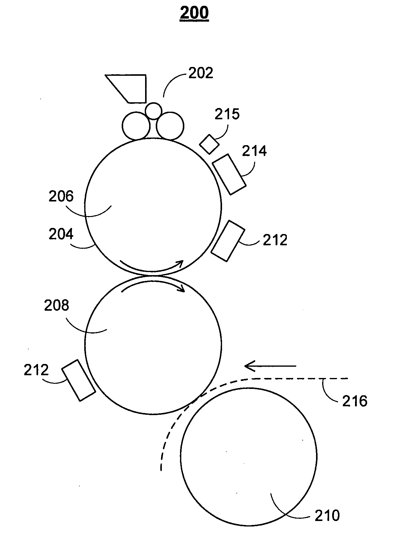
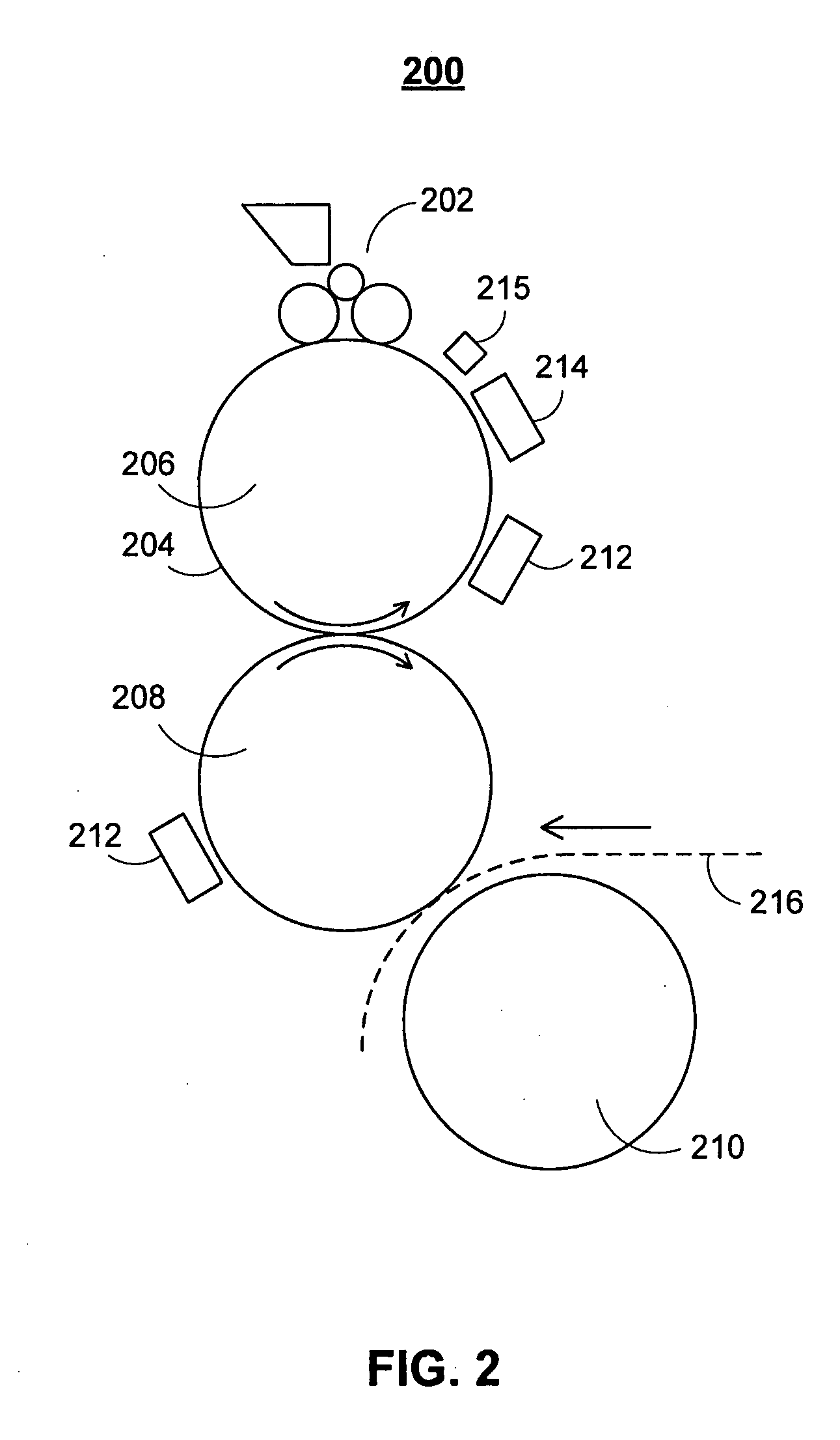
[0014] In some embodiments, the high speed variable printing apparatus is in communication with a back-end database management system. The database management system may be in communication with one or more image controllers that control the operation of the aqueous jet and lithographic systems to provide a versatile, user-reconfigurable variable printing apparatus.

Problems solved by technology

These wetted areas will not accept oil-based ink when the plate passes through an inking system.

Method used


Image

  • Systems and methods for high speed variable printing
  • Systems and methods for high speed variable printing
  • Systems and methods for high speed variable printing

Examples


Embodiment Construction

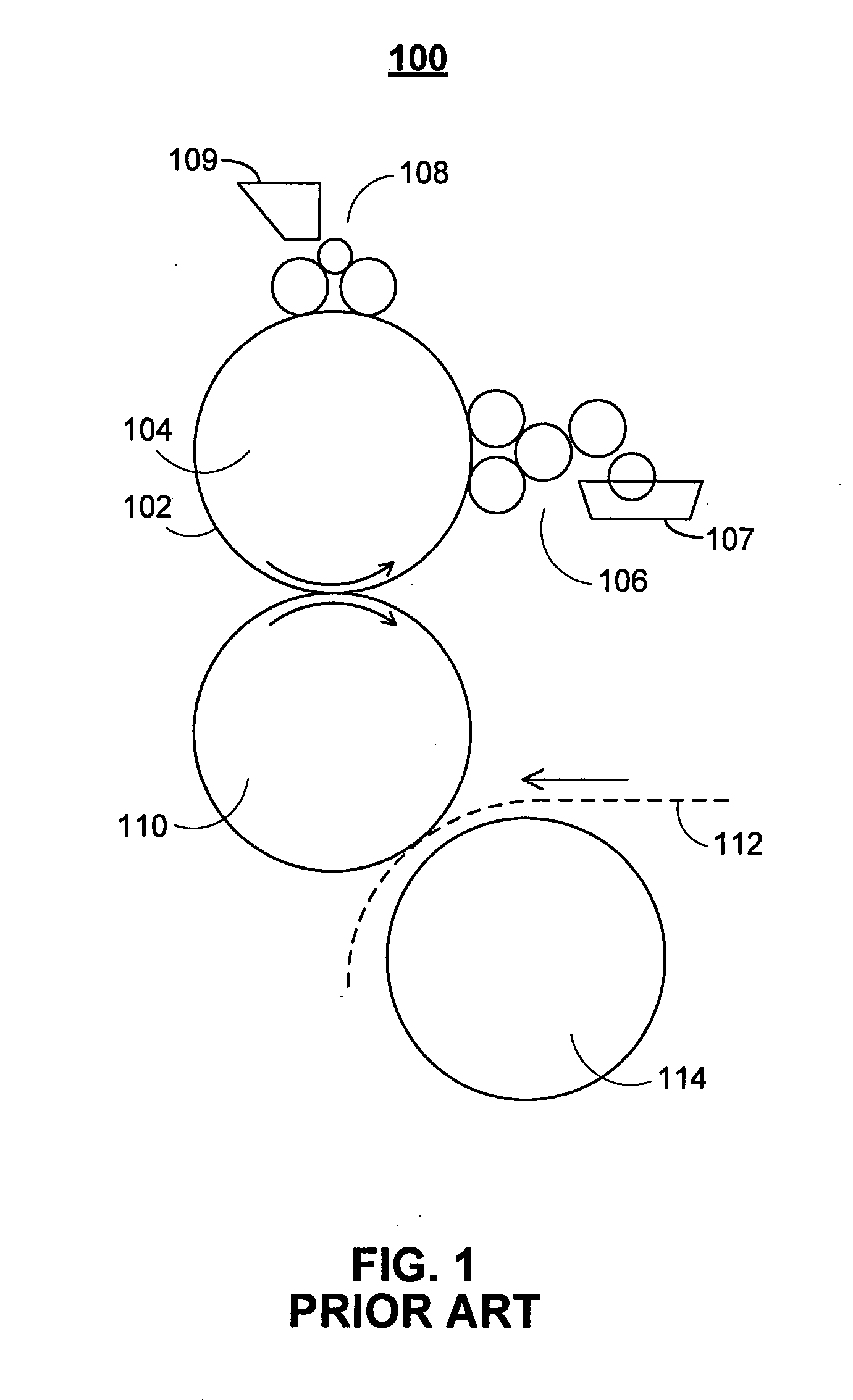
[0033]FIG. 1 illustrates traditional offset lithographic printing deck 100. In a traditional lithographic process, the image to be printed is etched onto hydrophilic plate 102 to create hydrophobic regions on the plate which will be receptive to ink. Hydrophilic plate 102 is mounted on plate cylinder 104 and rotated through dampening system 106 and inking system 108. Dampening system 106 may include water supply 107, and inking system 108 may include ink source 109. The hydrophilic portions of plate 102 are wetted by dampening system 106. By using an oil-based ink, ink is only received by the hydrophobic portions of plate 102.

[0034] If a blanket cylinder is used, such as blanket cylinder 110, the inked image may be transmitted from plate cylinder 104 to blanket cylinder 110. Then, the image may be further transferred to web 112 (e.g., paper) between blanket cylinder 110 and impression cylinder 114. Using impression cylinder 114, the image transfer to web 112 may be accomplished by ...


PUM


Abstract

Systems and methods for high-speed variable printing are provided. Ink jet technology and lithographic systems may be combined in such a way to create a fully variable and high-quality print system. An aqueous solution is applied to a cylinder to produce a negative image. The aqueous solution may comprise a block copolymer capable of physical bonding with the cylinder. Ink is then applied to the cylinder, and a positive image is transferred in ink to a print medium. The systems and methods described herein may be used to create high-quality one-to-one marketing applications.

Description

CROSS-REFERENCE TO RELATED APPLICATIONS [0001] This application claims the benefit of U.S. Provisional Patent Application Nos. 60 / 775,511, filed Feb. 21, 2006 and 60 / 819,301, filed Jul. 7, 2006, both of which are hereby incorporated by reference herein in their entireties.BACKGROUND OF THE INVENTION [0002] Lithographic and gravure printing techniques have been refined and improved for many years. The basic principle of lithography is transferring ink from a surface having both ink-receptive and ink-repellent areas. Offset printing incorporates an intermediate transfer of the ink. For example, an offset lithographic press may transfer ink from a plate cylinder to a rubber blanket cylinder, and then the blanket cylinder transfers the image to the web (i.e., paper). In gravure printing, a cylinder with engraved ink wells makes contact with a web of paper and an electric charge helps transfer the ink onto the paper. [0003] Early implementations of lithographic technology utilized relief...

Claims


Application Information

Patent Timeline
Patent Type & Authority Applications(United States)
IPC IPC(8): B41M1/14
CPCB41C1/105B41C1/1066B41F7/00B41F7/30B41F33/0054B41P2227/70B41J29/17B41M1/06B41M1/14B41P2200/13B41P2200/22B41J2/0057B41C2210/16B41C1/10B41F7/02B41J3/407B41F1/18
Inventor CYMAN, THEODORE F. JR.DEJOSEPH, ANTHONY B.HOOK, KEVIN J.HAAN, HENKMOSCATO, ANTHONY V.
Owner R R DONNELLEY & SONS CO
Learn More