Method and system for use of 3D sensors in an image capture device

a technology of image capture device and 3d sensor, which is applied in the field of digital cameras, can solve the problems of inability to directly obtain depth information, 2d sensors are unable to measure the distance from the sensor (depth), and 2d sensors lack the ability to measure the third dimension

Inactive Publication Date: 2007-08-30
LOGITECH EURO SA
View PDF2 Cites 182 Cited by
  • Summary
  • Abstract
  • Description
  • Claims
  • Application Information

AI Technical Summary

Benefits of technology

[0015] Measuring the depth of various points of the image using a 3D sensor provides direct information about the distance to various points in the image, such as the user's face, and the background. In one embodiment, such information is used for various applications. Examples of such applications include background replacement, image effects, enhanced automatic exposure / auto-focus, feature detection and tracking, authentication, user interface (UI) control, model-based compression, virtual reality, gaze correction, etc.

Problems solved by technology

2D sensors lack the ability to measure the third dimension (e.g., along the Z axis in a Cartesian coordinate system).
Thus, not only is the image created two-dimensional, but also, the 2D sensors are unable to measure the distance from the sensor (depth), of different portions of the image being captured.
Further, while a 3D image is created, depth information is still not directly obtained.
For several applications, the inability to measure the depth of different portions of the image is severely limiting.
It is difficult and inaccurate to distinguish between a user of a webcam and the background (e.g., chair, wall, etc.) using a two dimensional sensor alone, especially when some of these are of the same color.
However, 3D sensors have conventionally been very expensive, and thus use of such sensors in digital cameras has not been feasible.
However, measurements relating to depth are much more intensive than information relating to the other two dimensions.
Further, making the 2D pixels much larger to accommodate the 3D pixels is not desirable, since this will compromise the resolution of the 2D information.
Improved resolution in such cases implies increased size and increased cost.

Method used


Image

  • Method and system for use of 3D sensors in an image capture device
  • Method and system for use of 3D sensors in an image capture device
  • Method and system for use of 3D sensors in an image capture device

Examples


Embodiment Construction

[0025] The figures depict a preferred embodiment of the present invention for purposes of illustration only. It is noted that similar or like reference numbers in the figures may indicate similar or like functionality. One of skill in the art will readily recognize from the following discussion that alternative embodiments of the structures and methods disclosed herein may be employed without departing from the principles of the invention(s) herein. It is to be noted that the examples that follow focus on webcams, but that embodiments of the present invention could be applied to other image capturing devices as well.

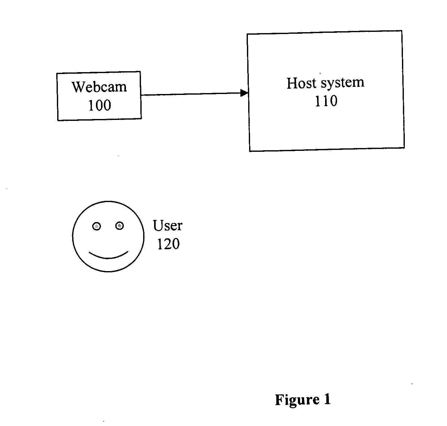
[0026]FIG. 1 is a block diagram illustrating a possible usage scenario with an image capture device 100, a host system 110, and a user 120.

[0027] In one embodiment, the data captured by the image capture device 100 is still image data. In another embodiment, the data captured by the image capture device 100 is video data (accompanied in some cases by audio data). In ye...


PUM


Abstract

The present invention is a system and method for the use of a 3D sensor in an image capture device. In one embodiment, a single 3D sensor is used, and the depth information is interspersed within the information for the other two dimensions so as to not compromise the resolution of the two-dimensional image. In another embodiment, a 3D sensor is used along with a 2D sensor. In one embodiment, a mirror is used to split incoming light into two portions, one of which is directed at the 3D sensor, and the other at the 2D sensor. The 2D sensor is used to measure information in two dimensions, while the 3D sensor is used to measure the depth of various portions of the image. The information from the 2D sensor and the 3D sensor is then combined, either in the image capture device or in a host system.

Description

BACKGROUND OF THE INVENTION [0001] 1. Field of the Invention [0002] This invention relates generally to digital cameras for capturing still images and video, and more particularly, to the use of 3D sensors in such cameras. [0003] 2. Description of the Related Art [0004] Digital cameras are increasingly being used by consumers to capture both still image and video data. Webcams, digital cameras connected to host systems, are also becoming increasingly common. Further, other devices that include digital image capturing capabilities, such as camera-equipped cell-phones and Personal Digital Assistants (PDAs) are sweeping the marketplace. [0005] Most digital image capture devices include a single sensor which is two-dimensional (2D). Such two dimensional sensors, as the name suggests, only measure values in two-dimensions (e.g., along the X axis and the Y axis in a Cartesian coordinate system). 2D sensors lack the ability to measure the third dimension (e.g., along the Z axis in a Cartes...

Claims


Application Information

Patent Timeline
Patent Type & Authority Applications(United States)
IPC IPC(8): G03B41/00
CPCG03B35/08H04N5/332H04N13/0257H04N13/0253H04N13/025H04N13/254H04N13/257H04N13/25H04N23/11
Inventor SARRAT, FREDERIC
Owner LOGITECH EURO SA
Why Eureka
Try Eureka