
Spurious tone suppressor and method of operation thereof

a tone suppressor and purifying technology, applied in the field of signal processing, can solve the problems of power management, complex power distribution systems for these environments, and increasing problems such as the interaction between the various subsystems,

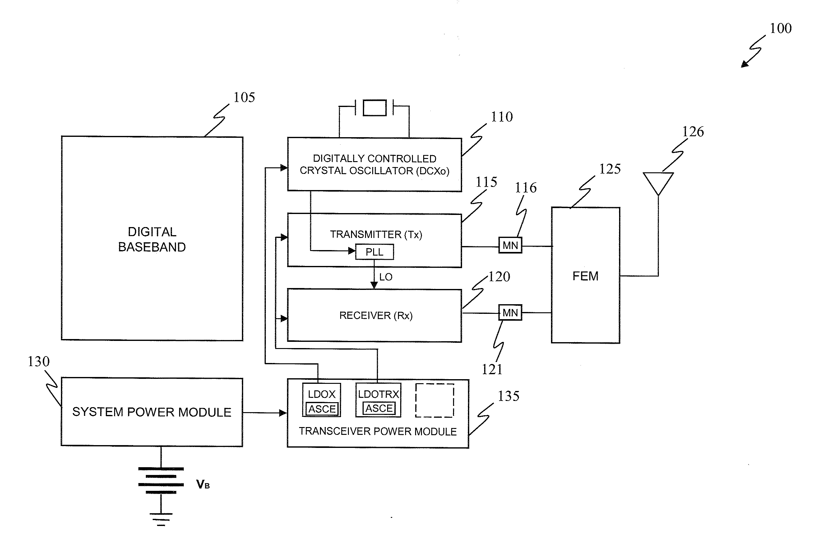
Inactive Publication Date: 2007-08-30
TEXAS INSTR INC
View PDF6 Cites 6 Cited by
  • Summary
  • Abstract
  • Description
  • Claims
  • Application Information

AI Technical Summary

Benefits of technology

The present invention provides a spurious tone suppressor for use with a power supply system. The suppressor includes an error signal generator and an adaptive spur cancellation engine. The error signal generator generates a spur error signal proportional to a spur signal associated with the power supply system. The adaptive spur cancellation engine processes the spur error signal to generate a corresponding anti-spur signal and injects it into the power supply system to suppress the spur signal. The technical effect of this invention is to reduce spur signals in a power supply system, improving the stability and efficiency of the system.

Problems solved by technology

As chip size is scaled downward, interactions between the various subsystems become increasingly problematic due to their closer proximity and reduced geometries.
Power distribution systems for these environments are also becoming more complex since the primary power source is usually a battery voltage that must be converted into several different supply voltages.
For these battery-based systems, power management has become a key design issue since extended operating time is often a highly desirable feature in a portable device.
Since the current drawn by the LDO load also passes through the regulator, this example requires that 3.2 volts be dropped across the regulator thereby wasting the significant portion of the power supplied to the regulator.
The wasted power would be generated as heat thereby contributing to other system problems, as well.
Spurs are particularly damaging to overall performance in areas that process low level and high frequency signals.

Method used


Image

  • Spurious tone suppressor and method of operation thereof
  • Spurious tone suppressor and method of operation thereof
  • Spurious tone suppressor and method of operation thereof

Examples


Embodiment Construction

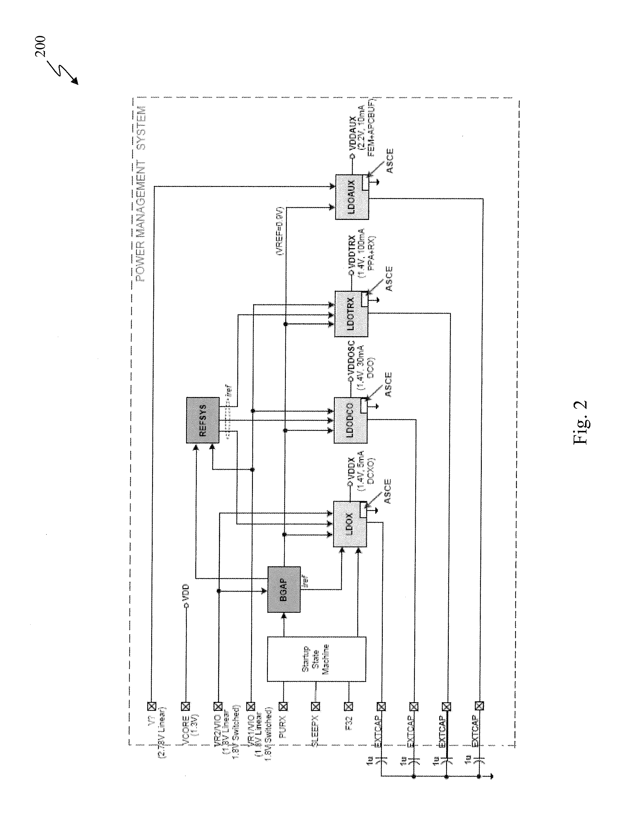
[0019]Embodiments of the present invention employ an adaptive spur cancellation technique, which injects a desired frequency signal of controlled amplitude and phase into a power system. The injected signal is determined by amplitude and phase components derived from in-phase (I) and quadrature-phase (Q) drive signals. Overall strength of these I and Q components determine the amplitude of cancellation energy provided to the power system, and relative strengths between these I and Q components determine the phase of the cancellation signal. Any of a plurality of potentially spur-generating clocking frequencies, employed within equipment supported by the power supply system, may be selected as an appropriate spur cancellation frequency. Additionally, an error signal representative of the spur signal may be derived from a plurality of collection points within the equipment. The error signal is then adaptively driven towards zero until the spur signal is forced to an acceptably low lev...


PUM


Abstract

The present invention provides a spurious tone suppressor for use with a power supply system. In one embodiment, the spurious tone suppressor includes an error signal generator configured to provide a spur error signal proportional to a spur signal associated with the power supply system. Additionally, the spurious tone suppressor also includes an adaptive spur cancellation engine coupled to the error signal generator and configured to adaptively process the spur error signal and generate a corresponding anti-spur signal that is injected into the power supply system to suppress the spur signal.

Description

CROSS-REFERENCE TO PROVISIONAL APPLICATION[0001]This application claims the benefit of U.S. Provisional Application No. 60 / 776,592 entitled “A Method for Spur Cancellation by Injecting Anti-Spur in the Power Supply System” to Khurram Muhammad and Chih-Ming Hung, filed on Feb. 24, 2006, which is incorporated herein by reference in its entirety.TECHNICAL FIELD OF THE INVENTION[0002]The present invention is directed, in general, to signal processing and, more specifically, to a spurious tone suppressor and a method of operating a spurious tone suppressor.BACKGROUND OF THE INVENTION[0003]The demand for wireless products has been growing in recent years resulting in intensive efforts to develop single chips that have reduced cost, power dissipation and chip size. As chip size is scaled downward, interactions between the various subsystems become increasingly problematic due to their closer proximity and reduced geometries. This is especially true for systems such as wireless transceivers...

Claims


Application Information

Patent Timeline
Patent Type & Authority Applications(United States)
IPC IPC(8): H04B1/10
CPCH04B15/005H04B1/123
Inventor MUHAMMAD, KHURRAMHUNG, CHIH-MING
Owner TEXAS INSTR INC
Learn More