Container apparatus of a vehicle

a technology of container apparatus and movable parts, which is applied in the directions of roofs, lock applications, transportation and packaging, etc., can solve the problems of difficult to locate the knob at the transverse end portion of the movable member, difficult to move the slider in the vertical direction via the knob, and the vertical size of the container apparatus can be compact, so as to improve the appearance of the external knob.

Inactive Publication Date: 2007-09-06
KOJIMA PRESS IND CO LTD +1
View PDF13 Cites 32 Cited by
  • Summary
  • Abstract
  • Description
  • Claims
  • Application Information

AI Technical Summary

Benefits of technology

[0016]Further, since the slider may extend and can be slidable in the longitudinal direction of the slider, by directing the longitudinal direction of the slider to a direction other than the vertical direction, for example, to the transverse direction (the right and left direction) of the vehicle, the vertical size of the container apparatus can be made compact.
[0017]Further, since the knob is of a push-type, there is no need to form a concave shaped portion in the member to which the knob device is provided to allow a finger for handling the knob to enter beneath the knob and at a rear side of the knob. Consequently, an external appearance of the knob may be improved. In contrast, in the conventional apparatus having a rotatable knob, the concave shaped portion is required.

Problems solved by technology

(a) It may be difficult to locate the knob at a position offset from the transverse center of the movable member.
As a result, it can be difficult to move the slider in the vertical direction via the knob.
This may mean that it is difficult to locate the knob at the transverse end portion of the movable member.
When the knob is provided to an upper box or a glove box in front of a front passenger seat of a vehicle at a transverse center of the upper box or the glove box, the knob can be positioned far away from a driver, whereby handling of the knob is not easy.
Since the knob is rotatably coupled to the movable member, the movable member is required to have the concave shaped portion to allow a finger to enter between the surface of the concave shaped portion and the knob, which makes the external appearance quality of the movable member low.

Method used


Image

  • Container apparatus of a vehicle
  • Container apparatus of a vehicle
  • Container apparatus of a vehicle

Examples


Embodiment Construction

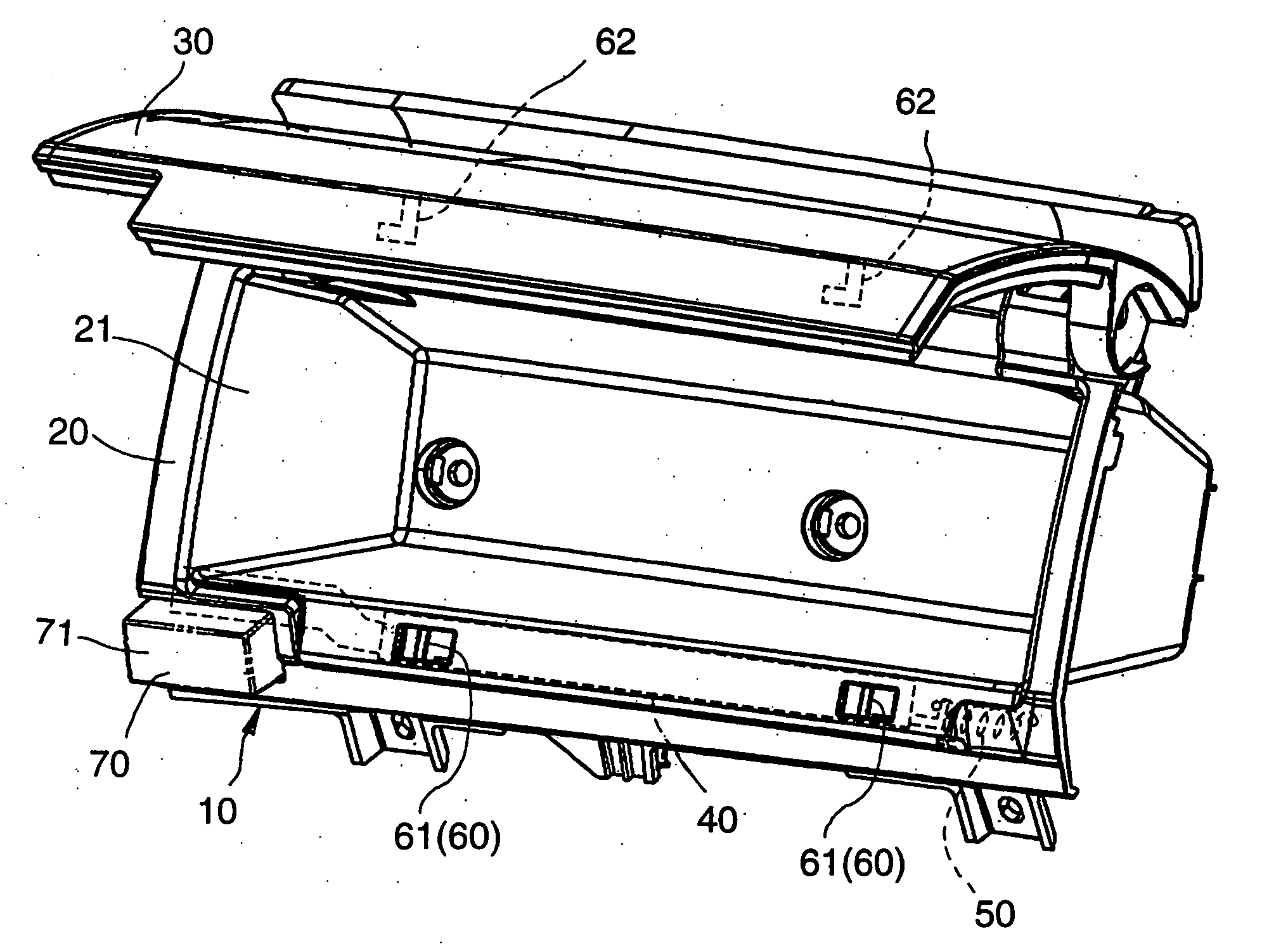
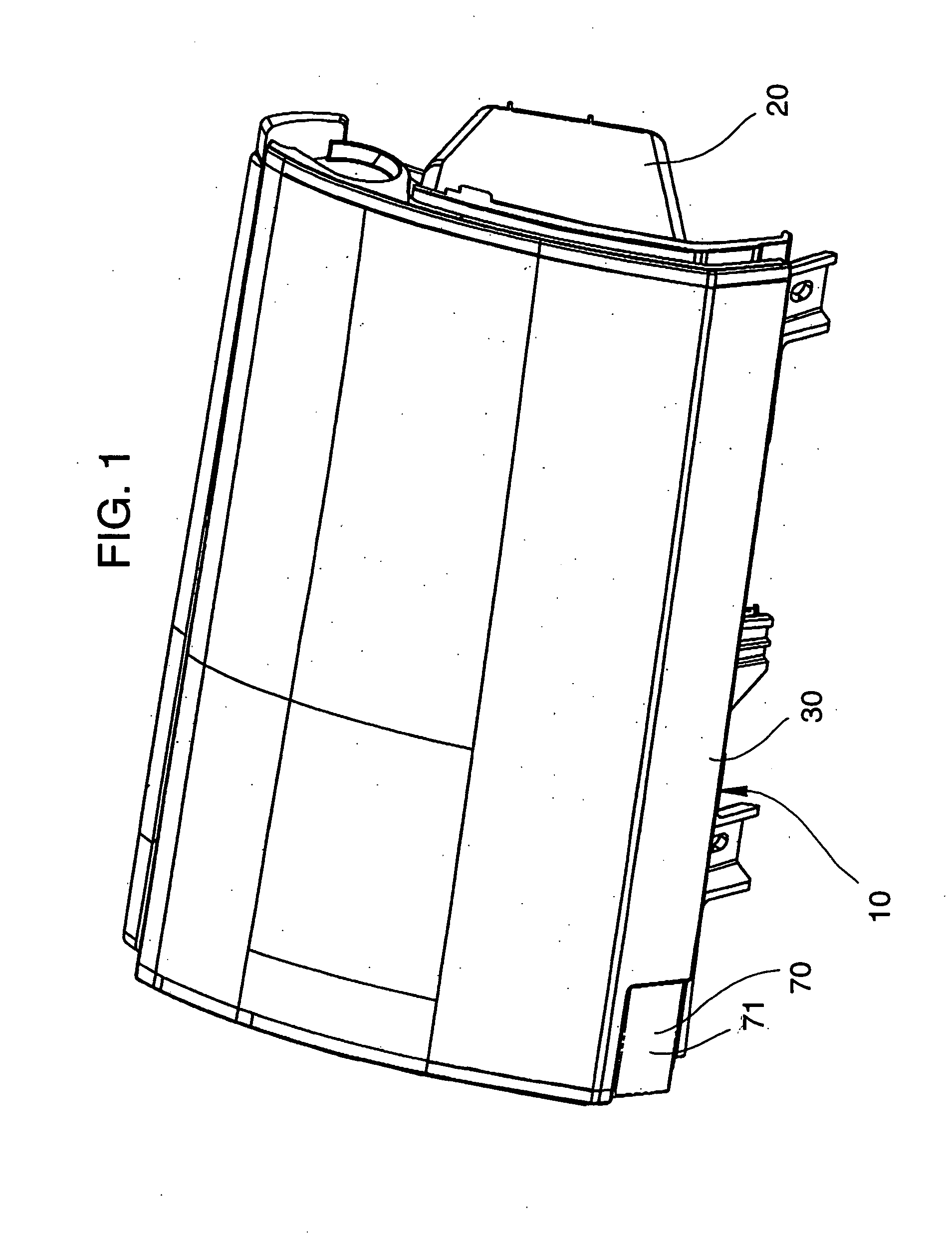
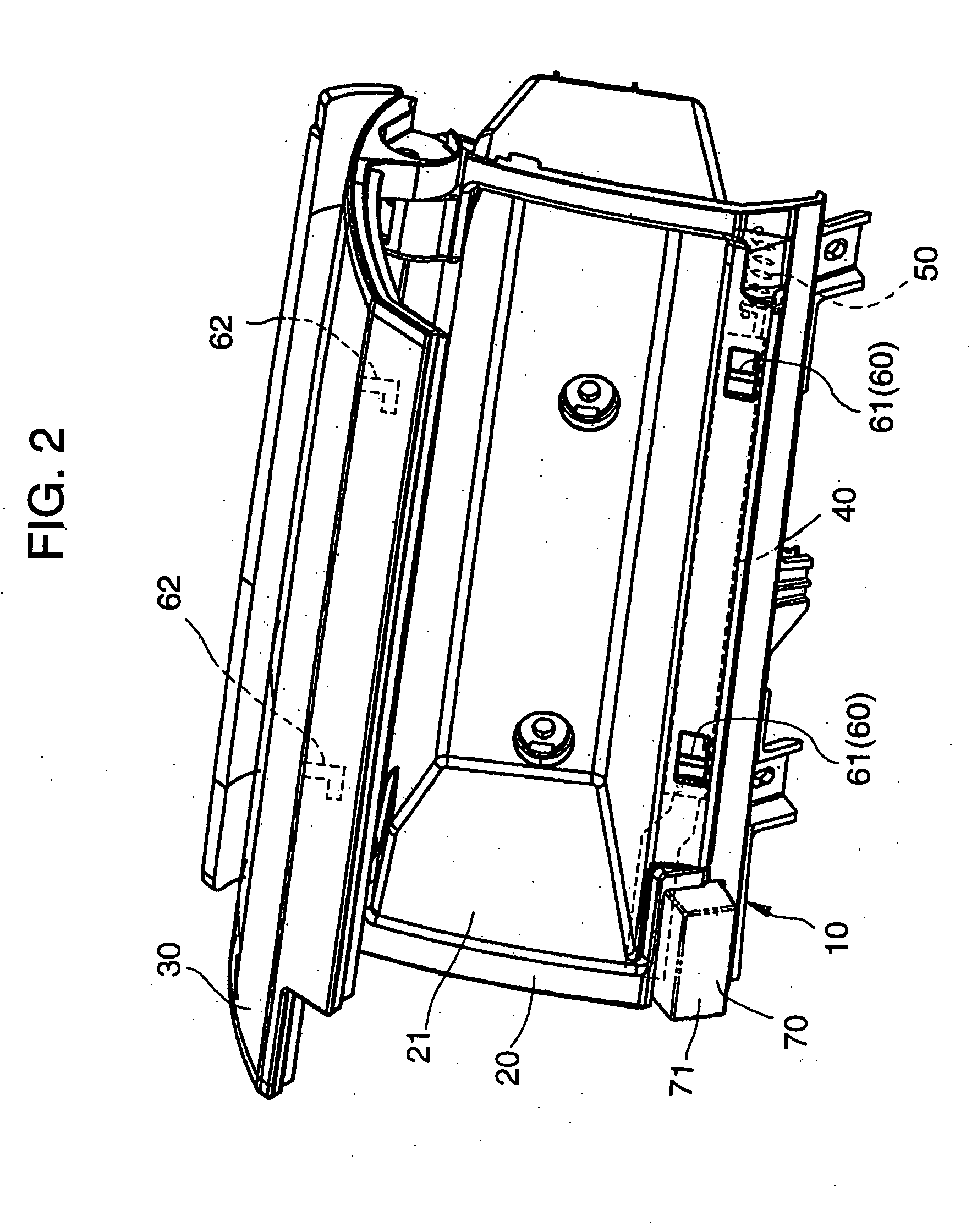
[0029]FIGS. 1-5 illustrate a container apparatus of a vehicle according to an embodiment of the present invention.

[0030]As illustrated in FIGS. 1 and 2, the container apparatus 10 of a vehicle according to an embodiment of the present invention is, for example, an upper box disposed at an instrument panel in front of a front passenger seat of the vehicle. The container apparatus 10 is not limited to the upper box, and may be a glove box disposed at the instrument panel in front of the front passenger seat of the vehicle, or another container of the vehicle or a cup holder of the vehicle disposed at the instrument panel or a position of the vehicle other than the instrument panel.

[0031]The container apparatus 10 of a vehicle includes a fixed member 20 and a movable member 20. As illustrated in FIG. 3, the container apparatus 10 further includes a slider 40, a slider biasing member 50, a lock device 60 and a knob device 70.

[0032]The fixed member 20 is fixed to the vehicle, for example...


PUM


Abstract

A container apparatus of a vehicle which may include (a) a fixed member, (b) a movable member movable relative to the fixed member, (c) a slider having a longitudinal direction and provided to a first member, which is one of the fixed member and the movable member, so as to be slidable relative to the first member, (d) a slider biasing member biasing the slider in one direction in the longitudinal direction of the slider, (e) a lock device having a hook engaging portion and a hook engageable with the hook engaging portion, one of the hook engaging portion and the hook being provided in the slider and the other of the hook engaging portion and the hook being provided in a second member which is the other of the fixed member and the movable member, and (f) a knob device provided to the first member and including a push-type knob which pulls the slider in a direction opposite the one direction in which the slider biasing member biases the slider.

Description

BACKGROUND[0001]1. Field of the Invention[0002]The present invention relates to a container apparatus of a vehicle.[0003]2. Description of Related Art[0004]Japanese Patent Publication 2003-148026 discloses a container apparatus of a vehicle which, as illustrated in FIGS. 6 and 7, includes a fixed member 1 fixed to a vehicle, a movable member 2 movable relative to the fixed member 1 so as to be pulled out from the fixed member and pushed into the fixed member, and a slider 3 provided slidably relative to the movable member 2 in a vertical direction. Two hook engageable portions 4 are provided on the fixed member 1 at portions of the fixed member different from each other in a transverse direction (a right and left direction) of the fixed member. Two hooks 5 are provided on the slider 3 so as to be engageable with the hook engageable portions 4 when the movable member is positioned in the fixed member. A knob 6 is provided in the movable member 2 at a transverse center of the movable ...

Claims


Application Information

Patent Timeline
Patent Type & Authority Applications(United States)
IPC IPC(8): B60P7/02
CPCE05B83/30B60R7/06
Inventor ISHIGURO, KEIKOZUKA, AKIHIKOCHIDA, MINORU
Owner KOJIMA PRESS IND CO LTD
Why Eureka
Try Eureka