Direct-view MEMS display devices and methods for generating images thereon

Inactive Publication Date: 2007-09-06
SNAPTRACK
View PDF102 Cites 172 Cited by
  • Summary
  • Abstract
  • Description
  • Claims
  • Application Information

AI Technical Summary

Benefits of technology

[0007] In contrast to projection displays in which switching circuitry and light modulators can be built on relatively small die cut from silicon substrates, most direct-view displays require the fabrication of light modulators on much larger substrates. In addition, in many cases, particularly for backlit direct view displays, both the control circuitry and the light modulators are p

Problems solved by technology

Direct-view displays using mechanical light modulators have not yet demonstrated sufficiently attractive combinations of brightness and low power.

Method used


Image

  • Direct-view MEMS display devices and methods for generating images thereon
  • Direct-view MEMS display devices and methods for generating images thereon
  • Direct-view MEMS display devices and methods for generating images thereon

Examples


Embodiment Construction

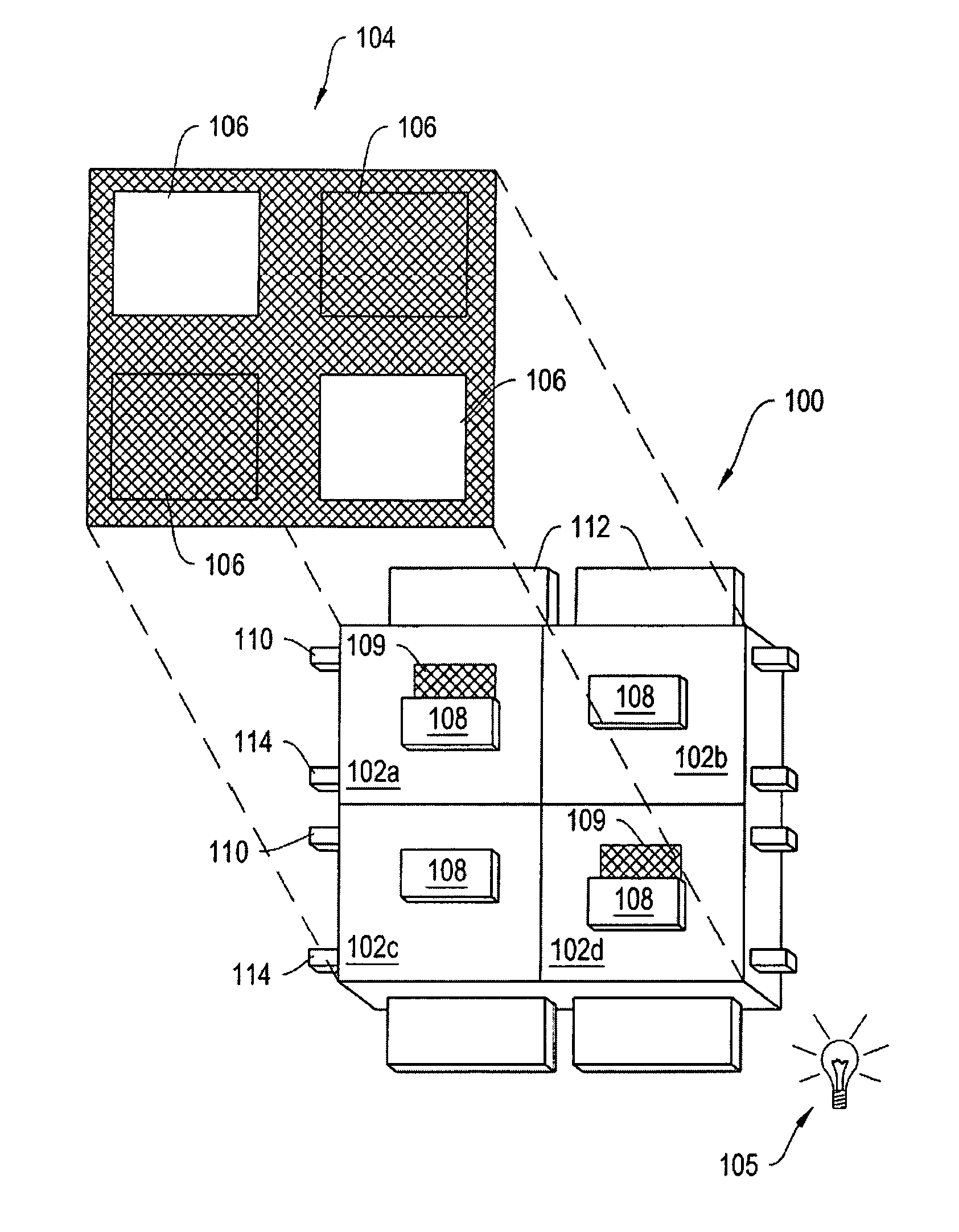
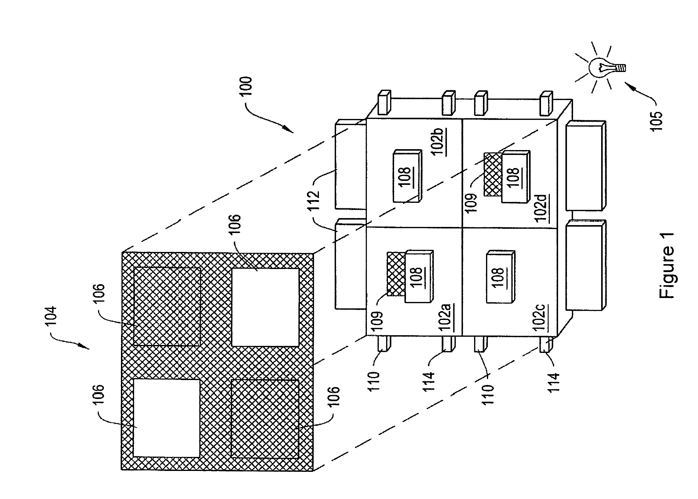
[0057]FIG. 1 is a schematic diagram of a direct-view MEMS-based display apparatus 100, according to an illustrative embodiment of the invention. The display apparatus 100 includes a plurality of light modulators 102a-102d (generally “light modulators 102”) arranged in rows and columns. In the display apparatus 100, light modulators 102a and 102d are in the open state, allowing light to pass. Light modulators 102b and 102c are in the closed state, obstructing the passage of light. By selectively setting the states of the light modulators 102a-102d, the display apparatus 100 can be utilized to form an image 104 for a backlit display, if illuminated by a lamp or lamps 105. In another implementation, the apparatus 100 may form an image by reflection of ambient light originating from the front of the apparatus. In another implementation, the apparatus 100 may form an image by reflection of light from a lamp or lamps positioned in the front of the display, i.e. by use of a frontlight.

[00...


PUM


Abstract

A direct-view display includes an array of MEMS light modulators and a control matrix formed on a transparent substrate, where each light modulator can be driven into at least two states, and a controller for controlling the states of each light modulator in the array. The control matrix transmits data and actuation voltages to the array. The controller includes an input, a processor, a memory, and an output. The input receives image data encoding an image frame for display. The processor derives a plurality of sub-frame data sets from the image data, where each sub-frame data set indicates desired states of light modulators in multiple rows and multiple columns of the array. The memory stores the plurality of sub-frame data sets. The output outputs the plurality of sub-frame data sets according to an output sequence to drive light modulators into the states indicated in the sub-frame data sets.

Description

CROSS-REFERENCE TO RELATED APPLICATIONS [0001] This application claims priority to and the benefit of U.S. Provisional Patent Application Ser. No. 60 / 751,909 filed Dec. 19 2005 and entitled “Methods and Apparatus for a Backlight for Color Displays.”[0002] This application also claims priority to and the benefit of U.S. Provisional Patent Application Ser. No. 60 / 776,367 filed Feb. 24, 2006 and entitled “Methods and Apparatus for a Backlight for Color Displays.”[0003] This application also is a continuation in part of and claims the benefit of U.S. Ser. No. 11 / 361,294 filed on Feb. 23, 2006, entitled “Devices Having MEMS Displays,” and published as U.S. Patent Application Publication No. 20060209012A1 on Sep. 21, 2006, which claims priority to and the benefit of U.S. Provisional Patent Application Ser. No. 60 / 655,827 filed Feb. 23, 2005 and U.S. Provisional Patent Application Ser. No. 60 / 676,053 filed Apr. 29, 2005. [0004] The disclosure of each of the foregoing applications is incorp...

Claims


Application Information

Patent Timeline
IPC IPC(8): G09G3/34
CPCG02B26/004G02B26/02G09G3/2003G09G3/2022G09G3/2081G09G3/3413G09G2360/144G09G5/06G09G5/363G09G5/393G09G2300/0809G09G2310/0235G09G2330/021G09G3/346G09G2310/0251G09G2310/08G09G2320/0247G09G2320/064G09G2320/066
Inventor HAGOOD, NESBITT W. IVGANDHI, JIGNESHMCALLISTER, ABRAHAMMALZBENDER, RAINER M.LEWIS, STEPHEN R.
Owner SNAPTRACK
Why Eureka
Try Eureka