
Printer with active fluidic architecture

a printing head and fluidic technology, applied in the field of printing, can solve the problems of clogging of the nozzle, affecting the quality of the print, and affecting the quality of the print, and achieve the effect of minimizing the bubble contamination of the printhead and avoiding visible artifacts

Inactive Publication Date: 2007-09-06
MEMJET TECH LTD +1
View PDF6 Cites 58 Cited by
  • Summary
  • Abstract
  • Description
  • Claims
  • Application Information

AI Technical Summary

Benefits of technology

[0012]a downstream pump mechanism in the downstream ink line.The invention gives the user active control of the ink flows from the ink reservoir to the nozzles of the printhead IC with the addition of a simple pump and valve. In the event that problems such as ink flooding, color mixing or printhead depriming occur, the user can follow simple troubleshooting protocols to rectify the situation.
[0014]Optionally, the printer further comprises a pressure regulator upstream of the printhead IC for maintaining ink in the nozzles at a hydrostatic pressure less than atmospheric pressure. Preferably, the ink supply is an ink tank upstream of the shut off valve, and the pressure regulator is positioned in the ink tank. In a further preferred form, the pressure regulator is a bubble point regulator which has an air bubble outlet submerged in the ink in the ink tank, and an air inlet vented to atmosphere such that any reduction of hydrostatic pressure in the in the ink tank because of ink consumption draws air through the air inlet to form bubbles at the bubble outlet and keep the pressure in the ink tank substantially constant.
[0037]The invention protects the ink in the ink supply from contaminants that can migrate up the ink line during shut down periods. The valve member is constantly biased to a closed position and so seals the ink supply from the printhead IC as a default condition even in the event of a power failure. The bias is strong enough to provide the fluid seal so that the seal is not compromised when the pressure difference between the inlet and the outlet is small.
[0047]Giving the printer user the ability to selectively pump ink through the fluidic architecture both upstream and down stream of the printhead IC, allows many of the problems associated with MEMS printheads to be corrected after they occur. In light of this, it is not as crucial that the printer components themselves safeguard against issues such as de-prime, color mixing and outgassing. An active control system for the ink flow through the printer means that the user can prime, deprime, or purge the printhead IC. Also, the upstream line can be deprimed and / or the downstream line can be deprimed (and of course subsequently re-primed). This control system allows the user to correct and print artifact causing conditions as and when they occur.
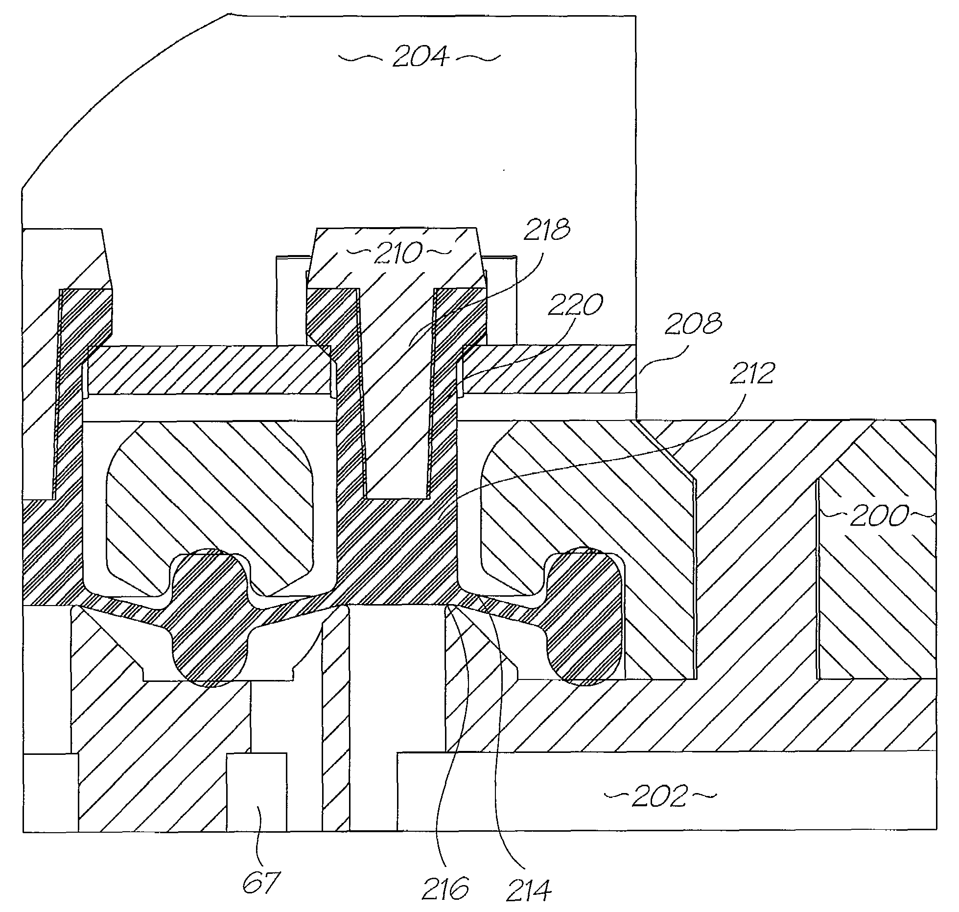
[0061]Outgassing from the ink into the small conduits of the LCP moulding can create readily visible artifacts in the print. Using an ink distribution member that has profiled conduits that use capillarity or other means to draw bubble into the downstream ink line, will help to minimize bubble contamination of the printhead IC. It can also be used to promote the preferential filling of conduits containing larger ink bubbles over those with smaller ink bubbles so that priming occurs more uniformly.

Problems solved by technology

The small nozzle structures and high nozzle densities can create difficulties with nozzle clogging, de-priming, nozzle drying (decap), color mixing, nozzle flooding, bubble contamination in the ink stream and so on.
Each of these issues can produce artifacts that are detrimental to the print quality.
In reality, the many different types of operating conditions, and mishaps or unduly rough handling during transport or day to day operation, make it impossible to address the above problems via the ‘passive’ control of component design, material selection and so on.

Method used


Image

  • Printer with active fluidic architecture
  • Printer with active fluidic architecture
  • Printer with active fluidic architecture

Examples


Embodiment Construction

[0095]The printers using prior art types of fluid architecture are exemplified by the disclosure in the Assignee's co-pending U.S. Ser. No. 11 / 014,769 (our docket RRC001US) which is incorporated herein by cross reference. For context, the printhead assembly from this printer design will be described before the embodiments of the present invention.

Printhead Assembly

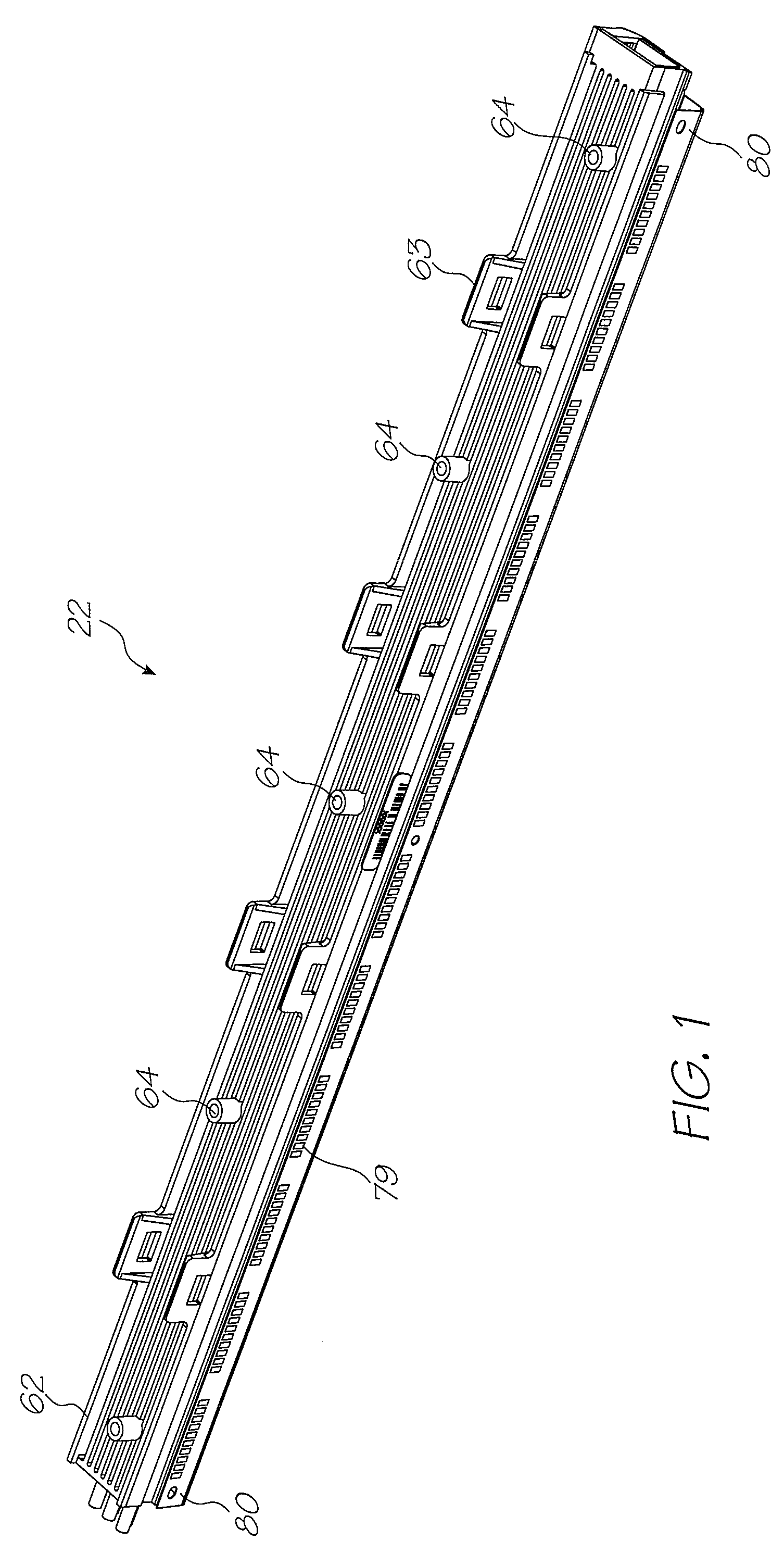
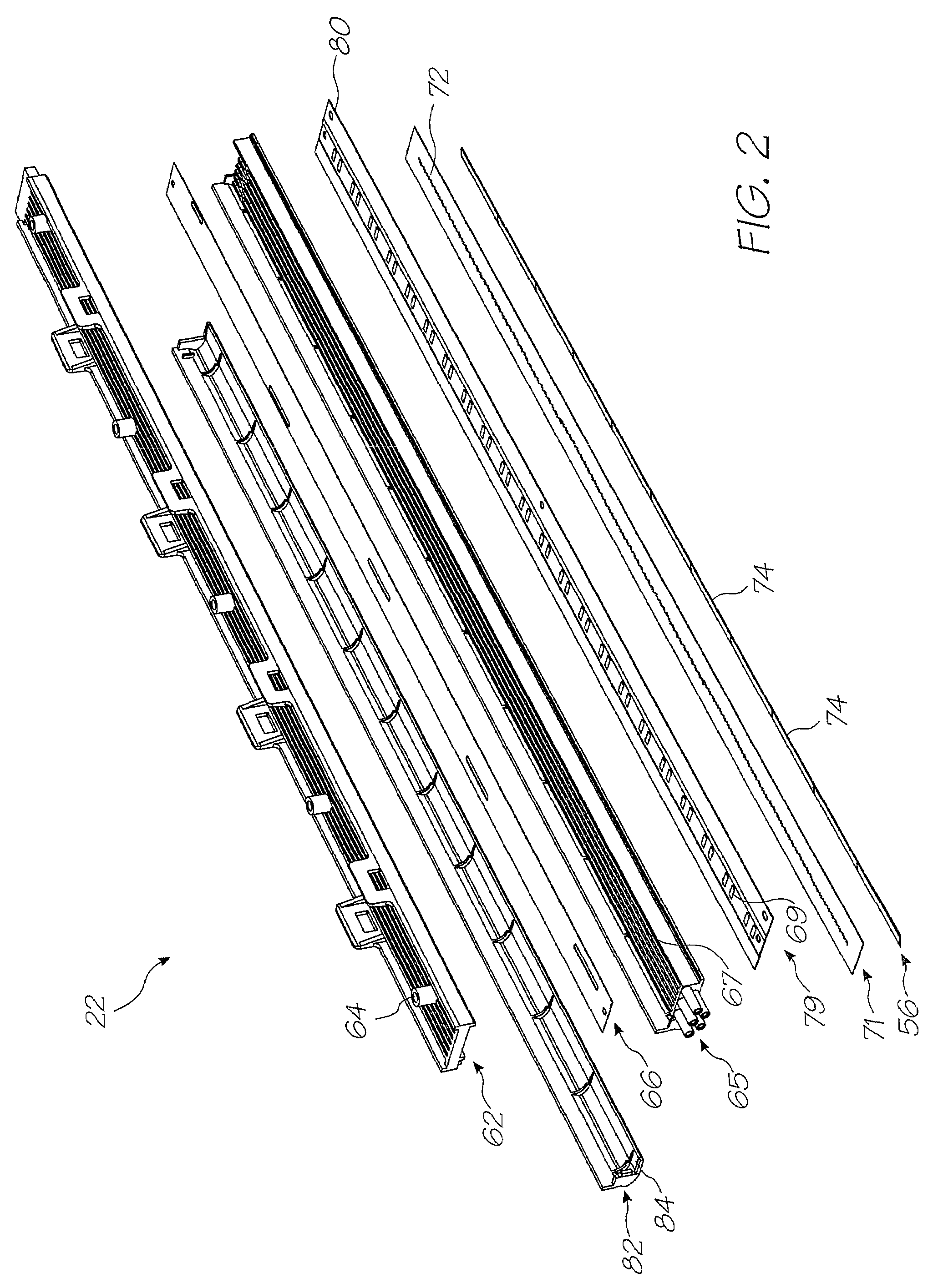
[0096]The printhead assembly 22 shown in FIGS. 1 to 4 is adapted to be attached to the underside of the main body 20 to receive ink from the outlets molding 27 (see FIG. 10 of U.S. Ser. No. 11 / 014,769, our docket RRC001US, cross referenced above).

[0097]The printhead assembly 22 generally comprises an elongate upper member 62 which is configured to extend beneath the main body 20 between the posts 26. U-shaped clips 63 project from the upper member 62. These pass through the recesses 37 provided in the rigid plate 34 and become captured by lugs (not shown) formed in the main body 20 to secure the printhead assembly 22.

[0098...


PUM


Abstract

A inkjet printer that has an ink supply (112), a printhead integrated circuit (IC) (74) in fluid communication with the ink supply via an upstream ink line (67), the printhead IC (74), a waste ink outlet in fluid communication with the printhead IC (74) via a downstream ink line (106), an upstream shut off valve (138) in the upstream ink line (67), and, a downstream pump mechanism (114) in the downstream ink line. With a valve upstream of the printhead and a pump downstream of the printhead, the user has active control of the ink flow upstream, downstream or in the printhead IC. In the event that problems such as ink flooding, color mixing or printhead depriming occur, the user can follow simple troubleshooting protocols to rectify the situation.

Description

FIELD OF THE INVENTION[0001]The present invention relates to the field of printing and in particular inkjet printing.COPENDING[0002]The following applications have been filed by the Applicant simultaneously with the present application:[0003]SBF007US SBF008US[0004]The disclosures of these co-pending applications are incorporated herein by reference. The above applications have been identified by their filing docket number, which will be substituted with the corresponding application number, once assigned.CROSS REFERENCES[0005]The following patents or patent applications filed by the applicant or assignee of the present invention are hereby incorporated by cross-reference.09 / 575197707971209 / 575123682594509 / 57516568130396987506703879769803186816274710277209 / 575186668104567280007173722708845909 / 5751817068382706265167891946789191664464265026146622999666938565499356987573672799665918846439706676011909 / 575198629034964281556785016687096668226396737591705573909 / 57512968301966832717695776809...

Claims


Application Information

Patent Timeline
Patent Type & Authority Applications(United States)
IPC IPC(8): B41J2/175
CPCB41J2/14B41J2/155B41J2/1707B41J2/175B41J2202/20B41J2002/14419B41J2002/14491B41J2202/19B41J2/17596B41J2/17556
Inventor MORGAN, JOHN DOUGLAS PETERMCAULIFFE, PATRICK JOHNKARPPINEN, VESAWORBOYS, DAVID JOHNWANG, MIAOSILVERBROOK, KIA
Owner MEMJET TECH LTD
Learn More