

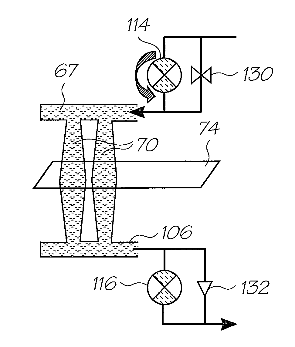
Printhead assembly with ink pump and shut off valve
- Summary
- Abstract
- Description
- Claims
- Application Information
AI Technical Summary
Benefits of technology
Problems solved by technology
Method used
Image

Examples
Embodiment Construction
[0097]The printers using prior art types of fluid architecture are exemplified by the disclosure in the Assignee's co-pending U.S. Ser. No. 11 / 014,769 (our docket RRC001US) which is incorporated herein by cross reference For context, the printhead assembly from this printer design will be described before the embodiments of the present invention.
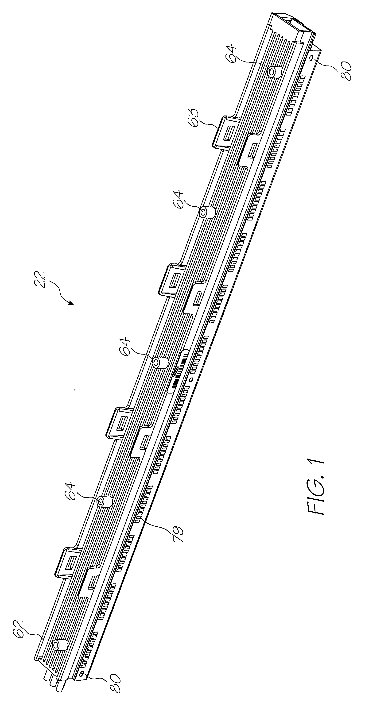
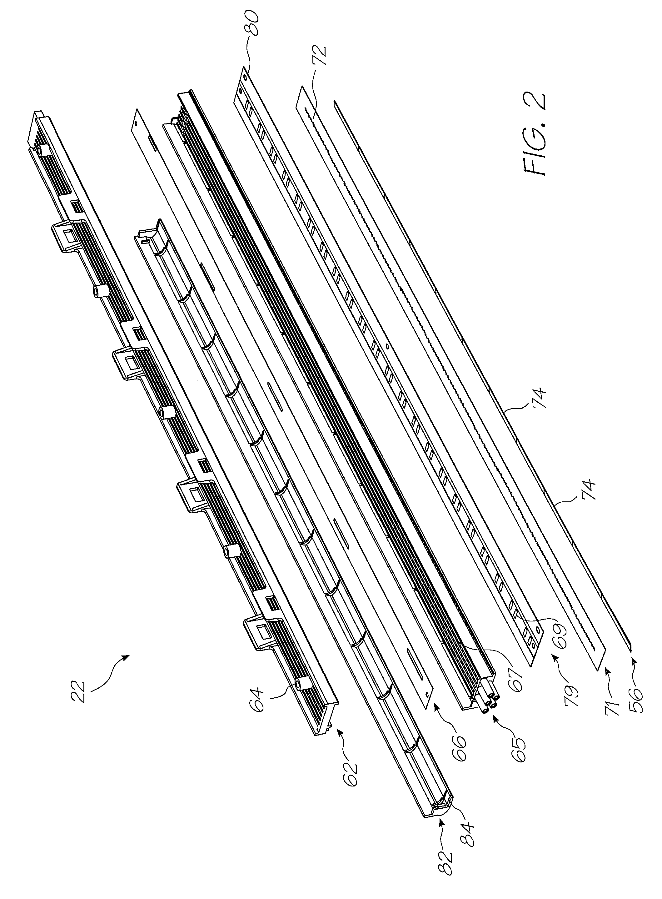
Printhead Assembly
[0098]The printhead assembly 22 shown in FIGS. 1 to 4 is adapted to be attached to the underside of the main body 20 to receive ink from the outlets molding 27 (see FIG. 10 of U.S. Ser. No. 11 / 014,769, our docket RRC001US, cross referenced above).
[0099]The printhead assembly 22 generally comprises an elongate upper member 62 which is configured to extend beneath the main body 20 between the posts 26. U-shaped clips 63 project from the upper member 62. These pass through the recesses 37 provided in the rigid plate 34 and become captured by lugs (not shown) formed in the main body 20 to secure the printhead assembly 22.
[0100]...
PUM
 Abstract
Description
Claims
Application Information