Systems and methods for improving a resolution of an image

a system and resolution technology, applied in the field of imaging systems, can solve the problems of reducing the resolution of the neck in the plane, reducing the width of the neck, and compromising the ability to resolve fine structures, etc., and achieve the effect of improving the resolution of the imag

Active Publication Date: 2007-09-06
GENERAL ELECTRIC CO
View PDF18 Cites 85 Cited by
  • Summary
  • Abstract
  • Description
  • Claims
  • Application Information

AI Technical Summary

Benefits of technology

[0007] In one aspect, a method for improving a resolution of an image is provided. The method includes reconstructing an image of an initial portion of an object at an initial resolution, and reconstructing an additional portion of the object at an additional resolution.

Problems solved by technology

In certain instances the resolution is lower that needed for an anatomical region and hence the ability to resolve fine structures is compromised.
However, proximal to the shoulders, the width of the neck is much smaller and the DFOV reconstruction reduces an in-plane resolution in the neck.

Method used


Image

  • Systems and methods for improving a resolution of an image
  • Systems and methods for improving a resolution of an image
  • Systems and methods for improving a resolution of an image

Examples


Embodiment Construction

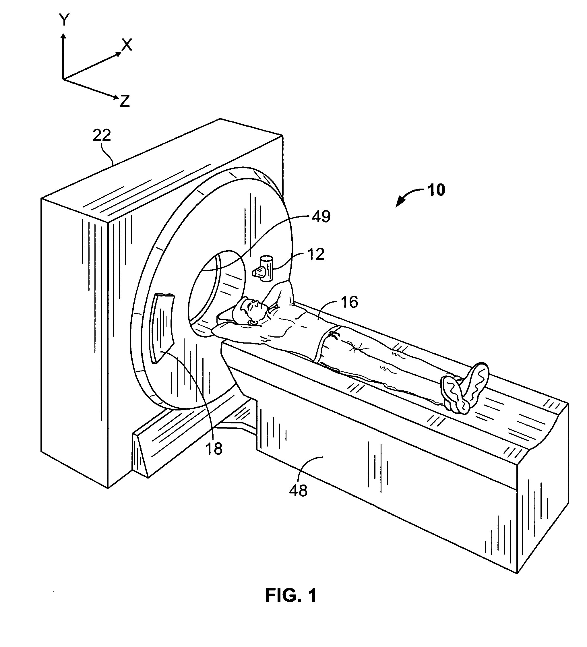
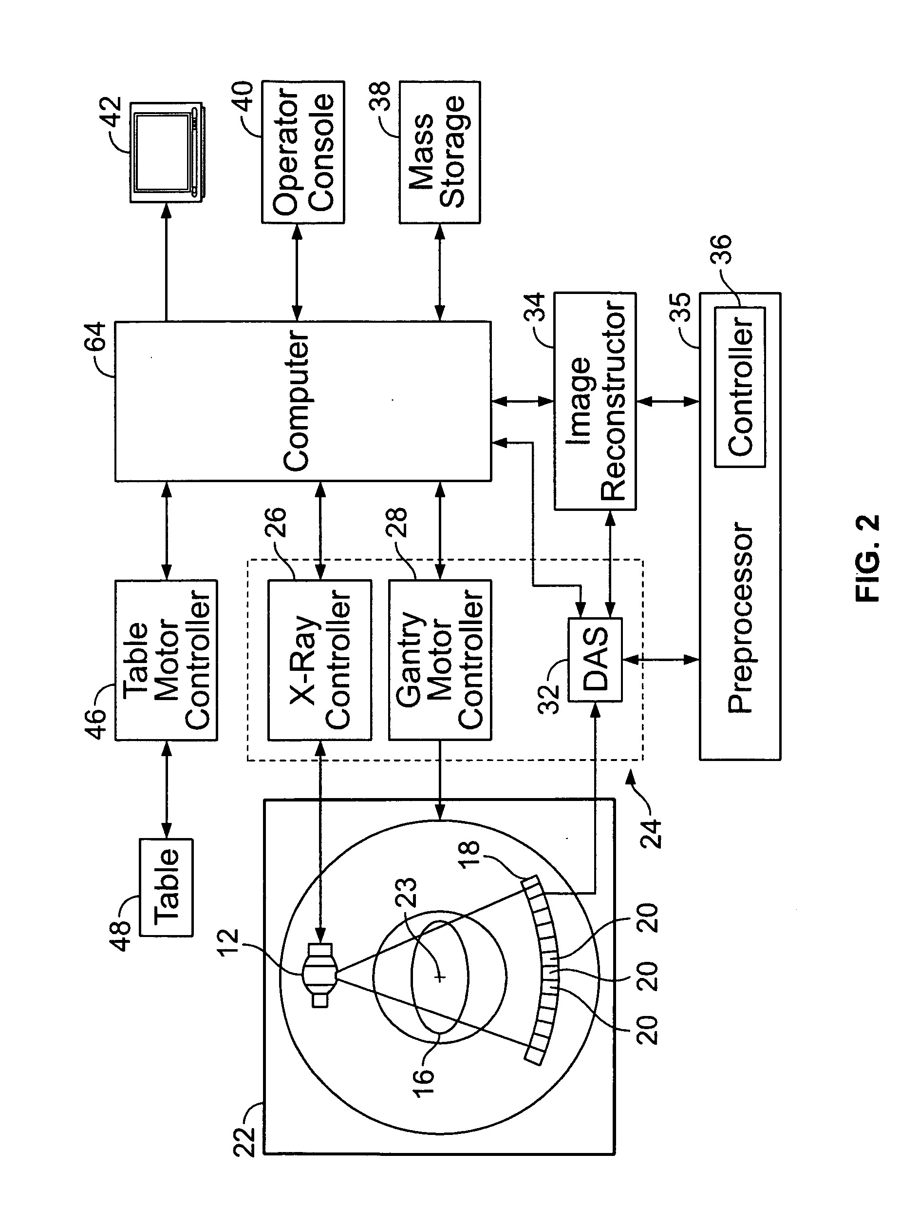
[0016]FIGS. 1 and 2 illustrate an embodiment of a computed tomography (CT) imaging system 10. CT imaging system 10 includes a gantry 22 and is a “third generation” CT system. In an alternative embodiment, CT system 10 may be an energy integrating, a photon counting (PC), or a photon energy discriminating (ED) CT detector system. Gantry 22 has an x-ray source 12 that projects a beam of x-rays toward a detector array 18. The x-rays pass through a subject 16, such as a patient, to generate attenuated x-rays. Subject 16 lies along a z-axis. A height of subject 16 is parallel to the z-axis. Detector array 18 is formed by a plurality of detector elements 20 which together sense the attenuated x-rays. A row of detector array 18 is located along an x-axis and a column of detector array 18 is located along a y-axis. In an alternative embodiment, each detector element 20 of detector array 18 may be a photon energy integrating detector, a photon counting, or a photon energy discriminating dete...


PUM

PropertyMeasurementUnit
widthaaaaaaaaaa
diameteraaaaaaaaaa
angleaaaaaaaaaa

Abstract

A method for improving a resolution of an image is provided. The method includes reconstructing an image of an initial portion of an object at an initial resolution, and reconstructing an additional portion of the object at an additional resolution.

Description

BACKGROUND OF THE INVENTION [0001] This invention relates generally to imaging systems and more particularly to, systems and methods for improving a resolution of an image. [0002] An imaging system includes a source that emits signals including, but not limited to, x-ray, radio frequency, or sonar signals, and the signals are directed toward a subject, such as a patient, to be imaged. The emitted signals and the interposed subject interact to produce a response that is received by one or more detectors. The imaging system then processes the detected response signals to generate an image of the subject. For example, in computed tomography (CT) imaging, an x-ray source projects a fan-shaped beam which is collimated to lie within an X-Y plane of a Cartesian coordinate system and generally referred to as the “imaging plane”. The x-ray beam passes through the subject being imaged. The beam, after being attenuated by the subject, impinges upon an array of radiation detectors. The intensit...

Claims


Application Information

Patent Timeline
Patent Type & Authority Applications(United States)
IPC IPC(8): H05G1/60G06K9/00A61B6/00G01N23/00G21K1/12
CPCA61B6/032A61B6/488G01N23/046G01N2223/612G06T11/005G01N2223/419G01N2223/66
Inventor SURYANARAYANAN, SRIKANTHLICATO, PAUL EDGARMALLYA, YOGISHAMAHAN, TARA JANEN
Owner GENERAL ELECTRIC CO
Why Eureka
Try Eureka