Methods and apparatus for error injection

a technology of error injection and apparatus, applied in the field of computer systems, can solve problems such as the inability of computer systems employing high-speed links to inject data errors

Inactive Publication Date: 2007-09-06
IBM CORP
View PDF10 Cites 32 Cited by
  • Summary
  • Abstract
  • Description
  • Claims
  • Application Information

AI Technical Summary

Problems solved by technology

In a conventional computer system, such errors may be inserted in the data by physically breaking the link and applying the errors to the link.
However, such a method of injecting errors in data may not be acceptable for a computer system employing a high-speed link.

Method used


Image

  • Methods and apparatus for error injection
  • Methods and apparatus for error injection
  • Methods and apparatus for error injection

Examples


Embodiment Construction

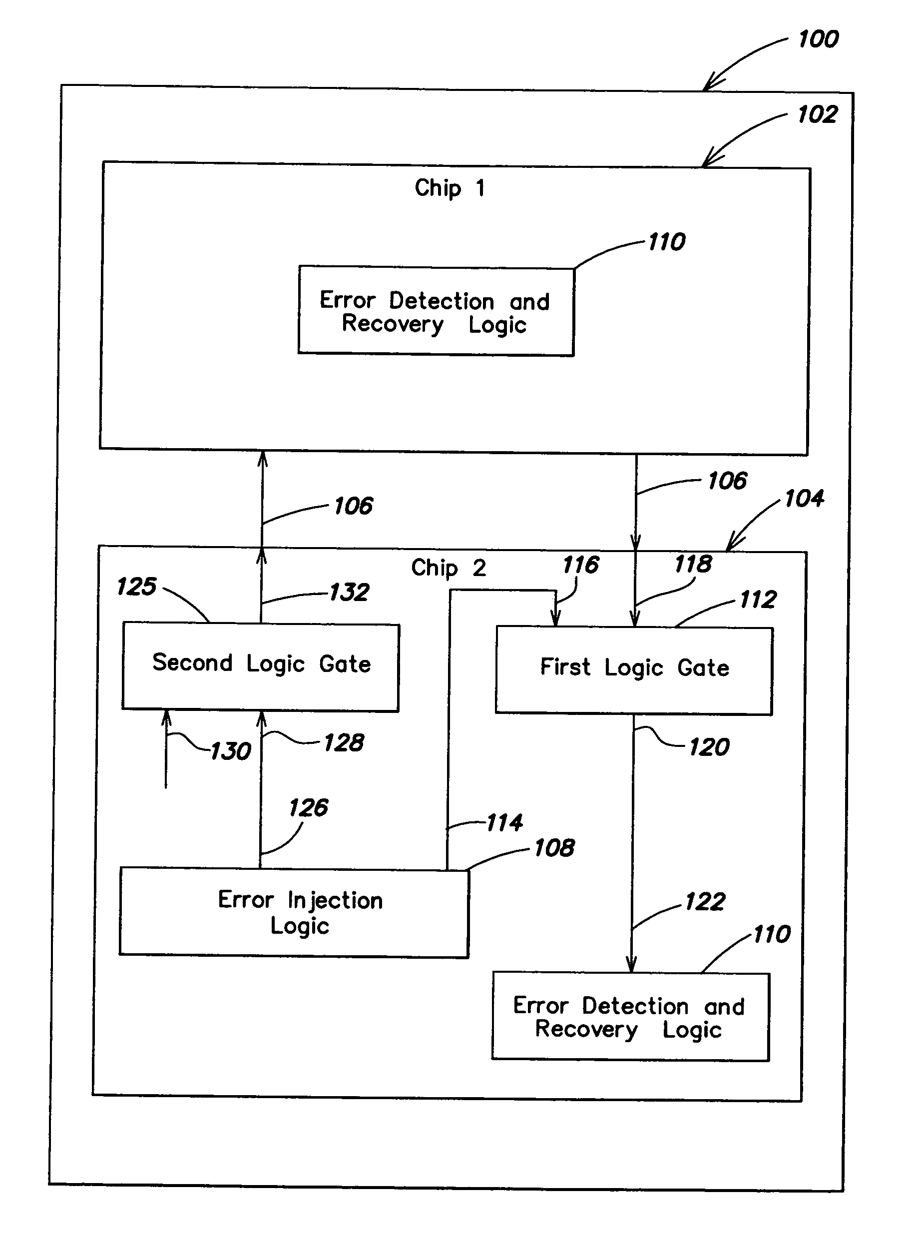
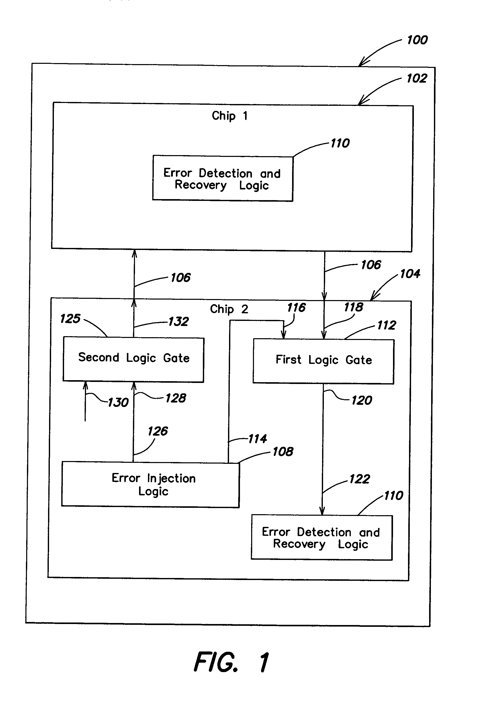
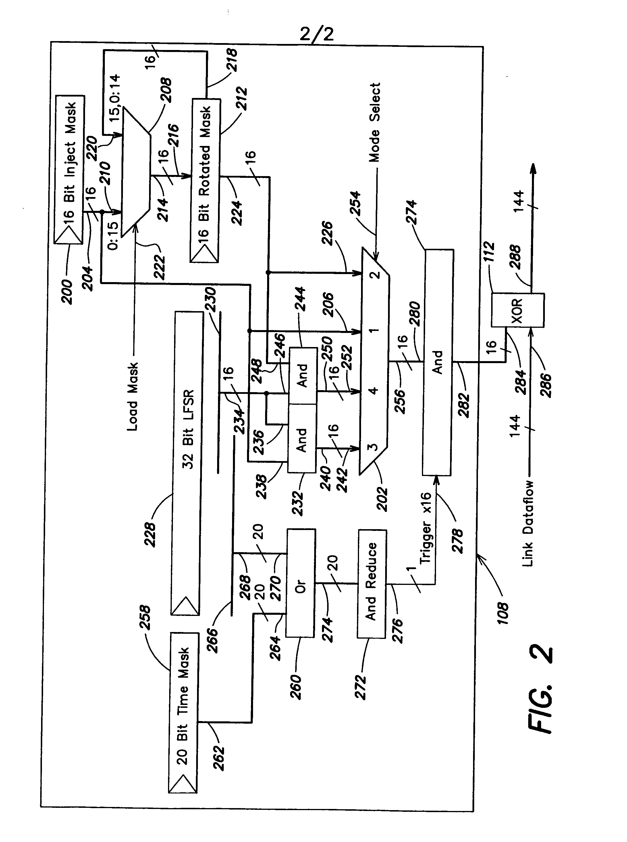
[0009] The present invention provides improved methods and apparatus for injecting one or more errors in data flowing into or out of a chip via a link. More specifically, the present invention may insert a pseudo-random error in data received by and / or transmitted from the chip via a link without breaking the link. The pseudo-random error may be based on an error injection pattern indicating one or more bits of the data on which the pseudo-random error is to be inserted and an error injection trigger indicating when such pseudo-random error is to be inserted in the data. The present invention may employ error injection logic to generate the error injection pattern and the error injection trigger. Such logic may be adapted to efficiently consume chip area. In this manner, the present invention provides improved methods and apparatus for injecting one or more errors in data flowing into or out of a chip.

[0010]FIG. 1 illustrates a system adapted to inject one or more errors in data in...


PUM


Abstract

In a first aspect, a first method of injecting one or more errors in data flowing into or out of a chip is provided. The first method includes the steps of (1) generating an error injection pattern indicating one or more bits of data on which a pseudo-random error is to be inserted; and (2) generating an error injection trigger indicating when the pseudo-random error is to be inserted. Numerous other aspects are provided.

Description

FIELD OF THE INVENTION [0001] The present invention relates generally to computer systems, and more particularly to methods and apparatus for error injection. BACKGROUND [0002] A computer system may include a chip adapted to receive data and / or transmit data via a link. The computer system may include logic (hereinafter “error detection and recovery logic”) adapted to detect one or more errors in the received data and enable the system to recover from such errors. To test the error detection and recovery logic, one or more errors may intentionally be injected into the data. In a conventional computer system, such errors may be inserted in the data by physically breaking the link and applying the errors to the link. However, such a method of injecting errors in data may not be acceptable for a computer system employing a high-speed link. Accordingly, improved methods and apparatus for error injection are desired. SUMMARY OF THE INVENTION [0003] In a first aspect of the invention, a f...

Claims


Application Information

Patent Timeline
Patent Type & Authority Applications(United States)
IPC IPC(8): G01R31/28
CPCG01R31/318569H04L43/50H04L41/0654H04L12/2697
Inventor CLARK, SCOTT D.RUEDINGER, JEFFREY JOSEPH
Owner IBM CORP
Why Eureka
Try Eureka