Supercharge Your Innovation With Domain-Expert AI Agents!

Failure protection apparatus for a pressure control assembly

Active Publication Date: 2007-09-13
MI
View PDF7 Cites 2 Cited by
  • Summary
  • Abstract
  • Description
  • Claims
  • Application Information

AI Technical Summary

Benefits of technology

[0009][[Thus, a safety mechanism has been invented to prevent the immediate loss of pressu

Problems solved by technology

However, maintenance of an optimum back pressure on the drilling fluid is complicated by variations in certain characteristics of the drilling fluid as it passes through the back pressure control device.
Therefore, the desired back pressure will not be achieved until appropriate changes have been made in the throttling of the drilling fluid in response to these changed conditions.
However, manual control of the throttling device involves a lag time and generally is inexact.
For a variety of reasons, including the failure of monitoring devices and operator error, pressure in the throttling area may be present.
When the external fluid source is disconnected, the choke member is no longer counterbalanced by the control fluid and the increased pressure is dissipated through the choke and any downstream equipment, causing potential damage to the equipment and risk of injury or death to people nearby.

Method used


Image

  • Failure protection apparatus for a pressure control assembly
  • Failure protection apparatus for a pressure control assembly
  • Failure protection apparatus for a pressure control assembly

Examples


Embodiment Construction

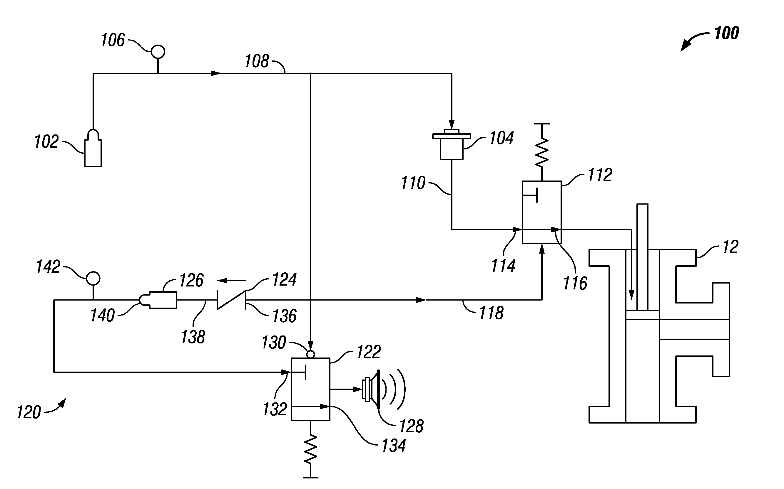
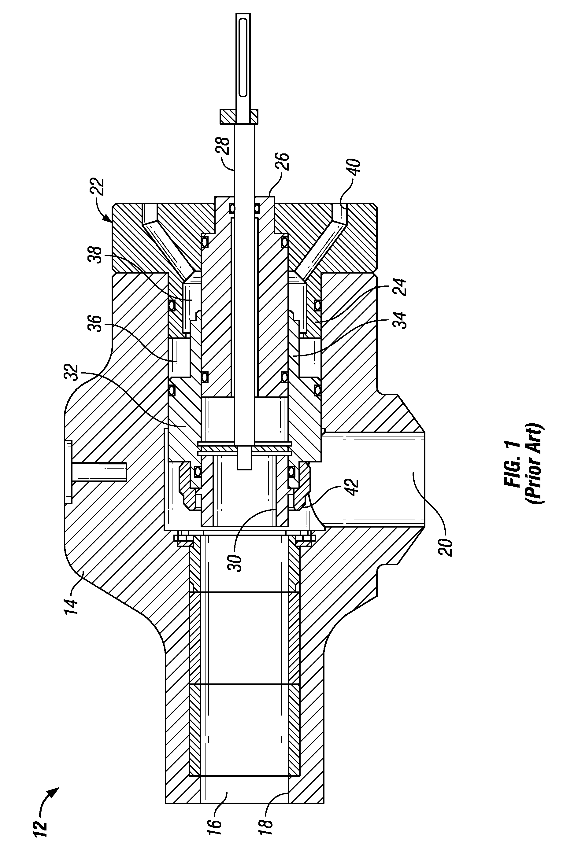
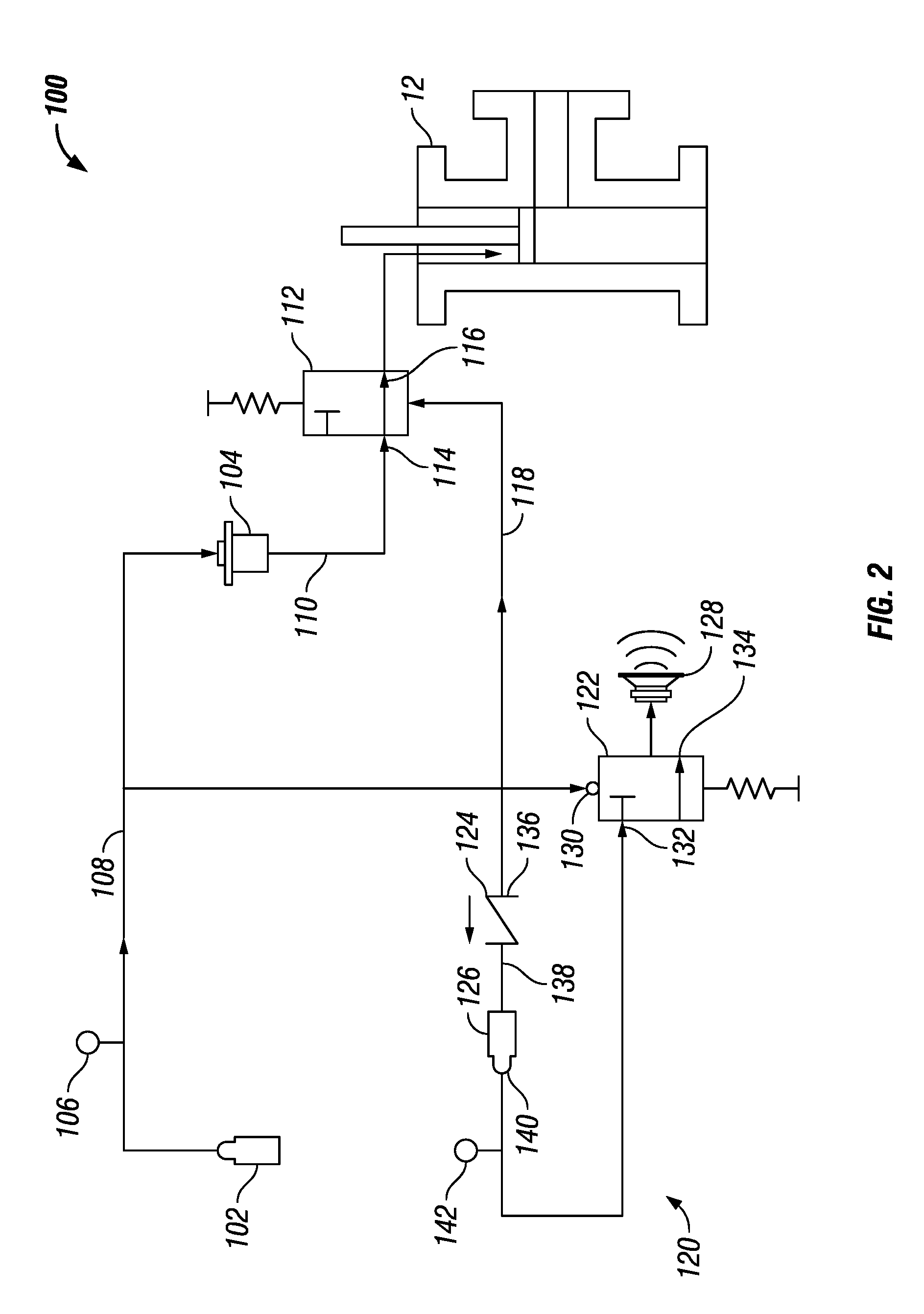
[0017]The claimed subject matter relates to a failure protection apparatus 100 (shown in FIG. 2) for a pressure control assembly 12 of the type shown in FIG. 1. Pressure control assembly 12 includes a housing 14 having an axial bore 16 extending through its length and having a discharge end 18. A radially extending inlet passage 20 is also formed in the housing 14 and intersects the bore 16. Drilling fluid from a downhole well is introduced into the inlet passage 20, passes through the housing 14 and normally discharges from the discharge end of the bore 16 for recirculation.

[0018]A bonnet 22 is secured to the end of the housing 14 opposite the discharge end 18 of the bore 16 of the housing. The bonnet 22 is substantially T-shaped in cross section and has a cylindrical portion 24 extending into the bore 16 of the housing. The interface between the bonnet 22 and the housing 14 is sealed. The bonnet 22 is fastened to the corresponding end of the housing 14.

[0019]A mandrel 26 is secure...


PUM


Abstract

The present invention provides a failure protection apparatus including an air source providing air having an air pressure, a first valve in fluid communication with the air source permitting fluid communication of a control fluid between a first fluid port and a second fluid port when the air pressure is at least a minimum air pressure and preventing fluid communication of the control fluid between the first fluid port and the second fluid port when the air pressure is below the minimum air pressure, a second valve in fluid communication with the air source preventing communication of air between an air inlet and an air outlet when the air pressure is at least the minimum air pressure and permitting communication of air between the air inlet and the air outlet when the air pressure is below the minimum air pressure, a third valve in fluid communication with the air source permitting communication of air to a third valve outlet when the air pressure is at least the minimum air pressure and preventing communication of air to the third valve outlet when the air pressure is below the minimum air pressure, a pressure container in fluid communication with the third valve outlet and having an air outlet, wherein the air outlet is in fluid communication with the air inlet of the second valve, and a warning device in fluid communication with the air outlet of the second valve and operable to emit sound when air is communicated from the air outlet.

Description

[0001]This application claims priority to Provisional Patent Application 60 / 780,093 filed on Mar. 8, 2006 and entitled, “A Failure Protection Apparatus for a Pressure Control Assembly” the contents of which are incorporated herein by reference for all purposes.BACKGROUND OF INVENTION [0002]This invention relates to an apparatus for freezing the set point pressure on a hydraulic choke when air pressure in the choke drops below a normal operating range and for returning the choke to normal operation when air pressure returns to the normal range.[0003]There are many applications in which there is a need to control the back pressure of a fluid flowing in a system. For example, in the drilling of oil wells, it is customary to suspend a drill pipe in the well bore with a bit on the lower end thereof and, as the bit is rotated, to circulate a drilling fluid, such as a drilling mud, down through the interior of the drill string, out through the bit, and up the annulus of the well bore to th...

Claims


Application Information

Patent Timeline
IPC IPC(8): F16K31/12F16K31/00F16K43/00F16K31/36
CPCE21B21/106F16K37/0066F16K31/122Y10T137/6164Y10T137/8326Y10T137/7792Y10T137/3115
Inventor BURKHARD, ALAN WAYNESAWYER, MICHAEL SCOTT
Owner MI
Features
  • R&D
  • Intellectual Property
  • Life Sciences
  • Materials
  • Tech Scout
  • Unparalleled Data Quality
  • Higher Quality Content
  • 60% Fewer Hallucinations
Learn More