Maximum Energy transfer through cell isolation and discharge

a cell isolation and maximum energy transfer technology, applied in the field of cell balancing in batteries, can solve the problems of battery pack inability to be fully charged, partial discharge of cells, and more slowly discharg

Inactive Publication Date: 2007-09-20
POWEREADY
View PDF1 Cites 20 Cited by
  • Summary
  • Abstract
  • Description
  • Claims
  • Application Information

AI Technical Summary

Problems solved by technology

This can result in fault conditions developing with the battery pack, and may also result in the only partial discharge of the cells which discharge more slowly.
This partial discharge can result in conditions where the battery pack can no longer be fully charged to achieve maximum cumulative battery pack capacity.

Method used


Image

  • Maximum Energy transfer through cell isolation and discharge
  • Maximum Energy transfer through cell isolation and discharge
  • Maximum Energy transfer through cell isolation and discharge

Examples


Embodiment Construction

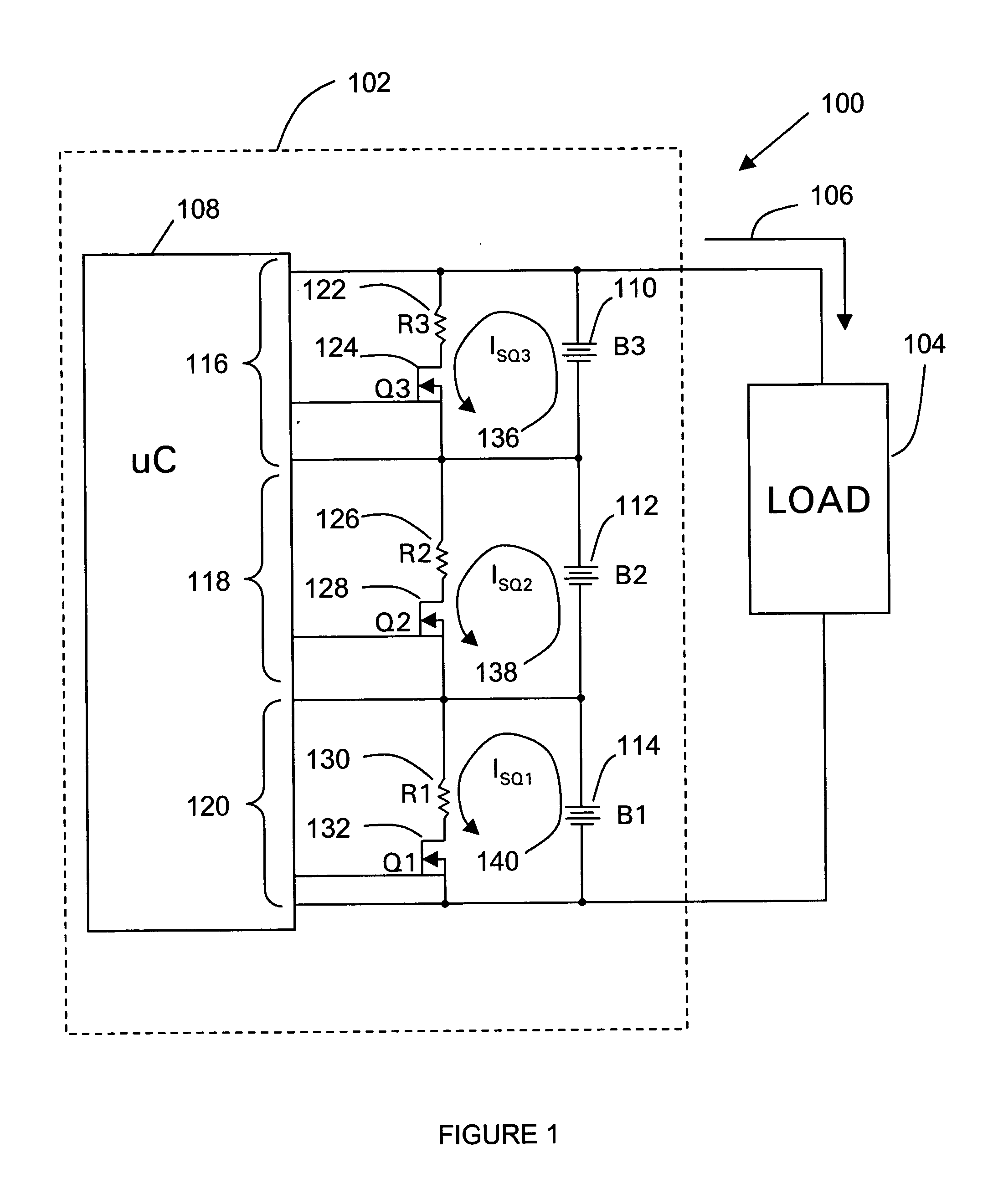
[0016] Referring to FIG. 1, a battery system of the present invention is shown and generally designated 100. System 100 includes a battery pack 102 in electrical communication with a load 104 that receives a current 106 from battery pack 102. In a preferred embodiment, the battery pack 102 includes a microcontroller 108 and a number of battery cells 110 (B3), 112 (B2), and 114(B1), in a series circuit configuration. The voltages of each cell 110, 112, and 114 are individually monitored by microcontroller 108, such as with a high-impedance input terminal. More specifically, the voltages of cells 110, 112 and 114 are measured by microcontroller 108 as voltage inputs 116, 118, and 120.

[0017] Across each cell 110, 112, and 114 is a transistor-resistor combination. Specifically, resistor 122 and transistor 124 are configured to provide an electrical circuit across cell 110 (B3). Similarly, resistor 126 and transistor 128 provide an electrical circuit across cell 112 (B2), and resistor 1...


PUM


Abstract

A battery system includes a multi-cell battery pack in electrical communication with a load. The voltages of each cell are individually monitored by the microcontroller, such as with a high-impedance input terminal. Across each of the cells is a transistor-resistor combination such that by providing a voltage to the gate of each of the transistors, a short-circuit is created through the corresponding cell thereby providing an additional current drain on the cell. More specifically, by turning on the transistor, a short-circuit current (ISQ1) is drawn from the cell through resistor (R1) to provide for the isolated discharge of the specific cell. By selectively measuring each of the cells in a multi-cell battery pack to determine if any of the cells are over-voltage, and if so, by increasing the current drain on that specific cell, the overall maximum amount of energy can be transferred to a load across the battery pack. Moreover, this selectively isolation and discharge provides a mechanism for maintaining a constant charge across all batteries in a multi-cell batter pack.

Description

RELATED APPLICATIONS [0001] This application claims the benefit of priority to U.S. Provisional Patent Application Ser. No. 60 / 501,542 filed Sep. 8, 2003, currently co-pending.FIELD OF THE INVENTION [0002] The present invention relates generally to a method of cell balancing in batteries. More specifically, the present invention pertains to a method of balancing the discharge levels for individual cells in a multi-cell battery pack, including all Lithium chemistry batteries. BACKGROUND OF THE INVENTION [0003]FIG. 2 presents a graph of a typical discharge curve for a multi-cell lithium chemistry battery pack, and is generally designated 200. Graph 110 includes three separate discharge voltage plots 202, 204, 206 representing the voltages of three separate cells within a typical battery pack. In a typical application, the cells within a battery pack are initially charged to a starting voltage 210. As the cells are applied to a load, the voltages within these cells decrease over time a...

Claims


Application Information

Patent Timeline
Patent Type & Authority Applications(United States)
IPC IPC(8): H02J7/00
CPCH02J7/0016H01M10/482Y02E60/10
Inventor CHANDLER, LANCE
Owner POWEREADY
Why Eureka
Try Eureka