Image forming apparatus and method for detecting separated state of transfer unit

a technology of transfer unit and image forming apparatus, which is applied in the direction of electrographic process apparatus, instruments, optics, etc., can solve the problems of increasing the number of components, increasing the cost, and detecting paper jams or the like may be subject to some constraints, and achieve the effect of low cos

Inactive Publication Date: 2007-09-20
KONICA MINOLTA INC
View PDF1 Cites 17 Cited by
  • Summary
  • Abstract
  • Description
  • Claims
  • Application Information

AI Technical Summary

Benefits of technology

[0013]According to the present invention, the pressure contact or separated stat...

Problems solved by technology

However, if the photointerrupter is used for detecting the pressure contact state and the separated state, the number of components increases, which causes increase of cost.
Therefore, it is ...

Method used


Image

  • Image forming apparatus and method for detecting separated state of transfer unit
  • Image forming apparatus and method for detecting separated state of transfer unit
  • Image forming apparatus and method for detecting separated state of transfer unit

Examples


Embodiment Construction

[0027]The invention will now be described in detail with reference to the attached drawings.

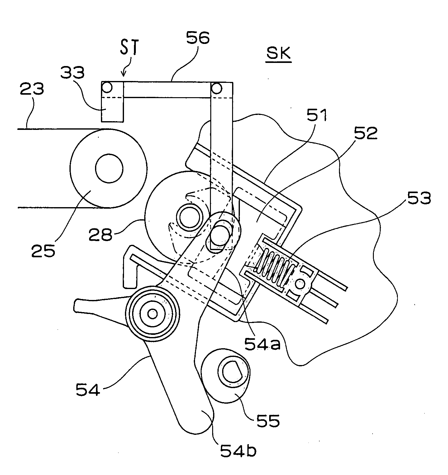
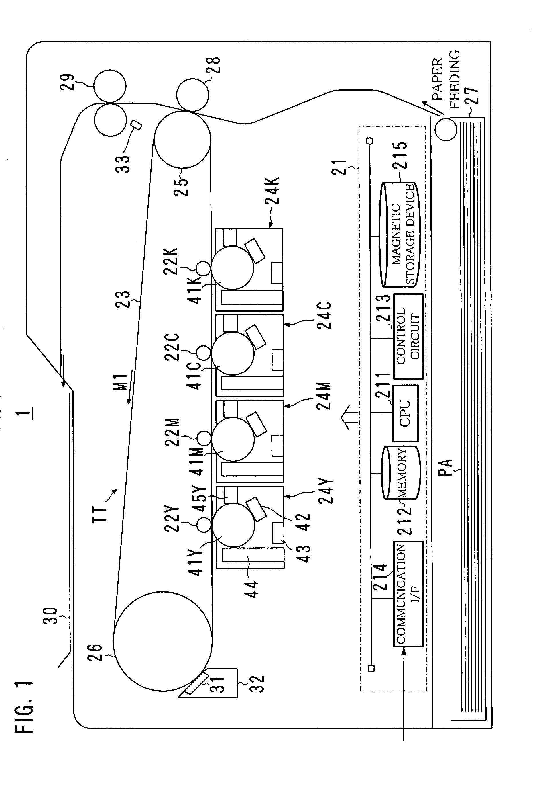
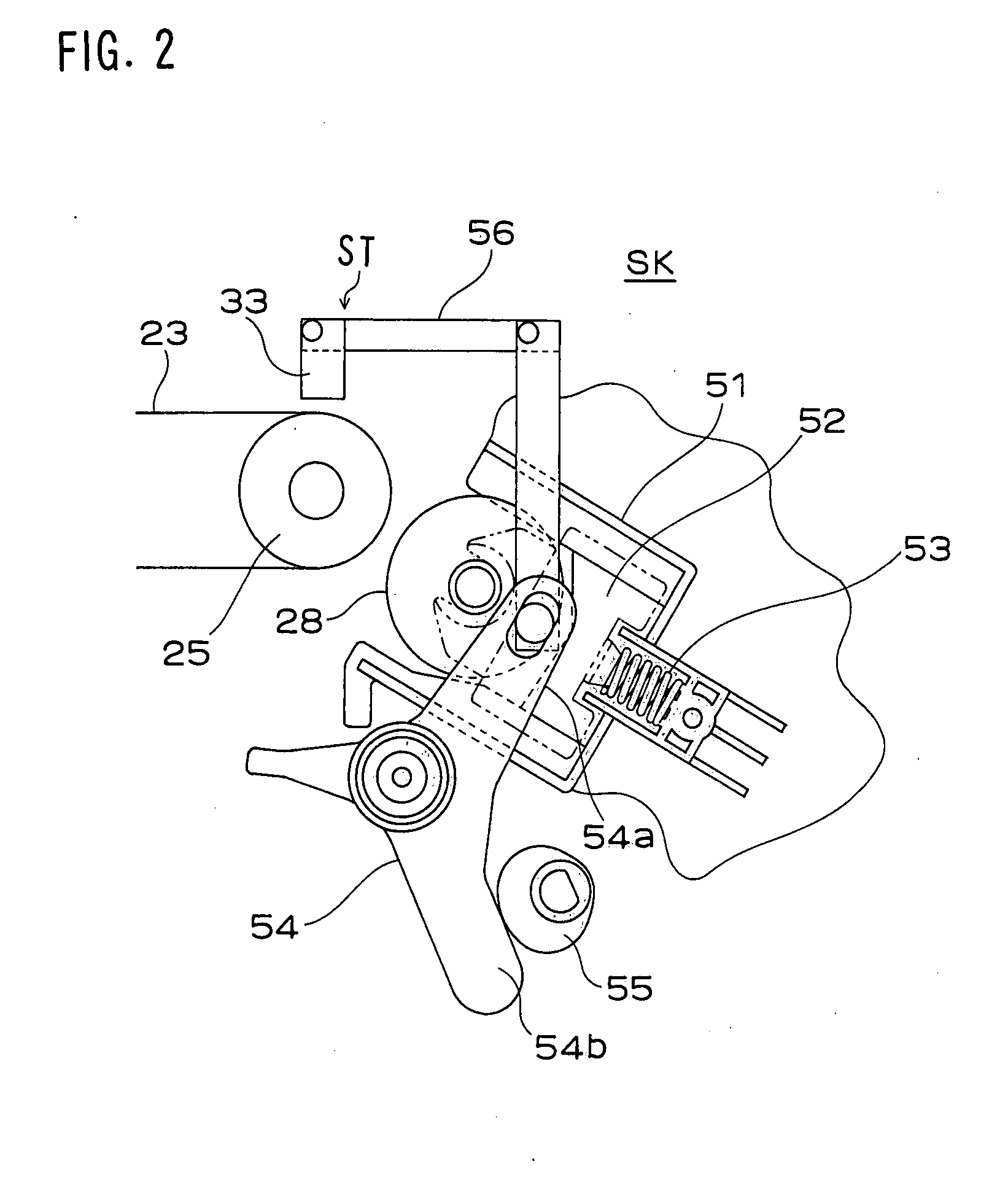
[0028]FIG. 1 is a diagram showing a general structure of an image forming apparatus 1 according to an embodiment of the present invention, FIGS. 2 and 3 are diagrams showing an example of a structure of a press and separation driving device SK, FIG. 4 shows an example of a toner patch, and FIG. 5 is a block diagram of an operation for stabilization. Note that FIG. 2 shows the case where a secondary transfer roller is in the separated state while FIG. 3 shows the case where the secondary transfer roller is in the pressure contact state.

[0029]As shown in FIG. 1, the image forming apparatus 1 is a digital mutifunction device or a printer that utilizes an electrophotographic technique and includes a tandem type print engine.

[0030]More specifically, the image forming device 1 includes image forming units 24Y, 24M, 24C and 24K of Y (yellow), M (magenta), C (cyan) and K (black) arranged in a line as...


PUM


Abstract

An image forming apparatus has a structure in which a toner image formed in an electrophotographic process is transferred from an intermediate transfer belt to a member to be transferred. The apparatus includes a secondary transfer roller that becomes a pressure contact state with respect to the intermediate transfer belt to make it perform a transfer process and can move between the pressure contact state and a separated state, and a press and separation driving device for driving the secondary transfer roller to become the pressure contact state and the separated state. The pressure contact state or the separated state of the secondary transfer roller is detected in accordance with a variation of an output of an IDC sensor for detecting a state of a bare surface of the intermediate transfer belt.

Description

[0001]This application is based on Japanese patent application No. 2006-072557 filed on Mar. 16, 2006, the contents of which are hereby incorporated by reference.BACKGROUND OF THE INVENTION[0002]1. Field of the Invention[0003]The present invention relates to an image forming apparatus such as a copying machine, a printer, an MFP, a facsimile machine, or a multifunction device thereof, and a method for detecting a pressure contact or separated state of a transfer unit in the image forming apparatus. For example, the present invention can be utilized for detecting a pressure contact or separated state of a secondary transfer roller with respect to an intermediate transfer belt.[0004]2. Description of the Prior Art[0005]Conventionally, a copying machine of an electrophotographic method, a printer, a facsimile machine, or an image forming apparatus such as a multifunction device called an MFP (Multi Function Peripherals) forms images by developing an electrostatic latent image formed on...

Claims


Application Information

Patent Timeline
IPC IPC(8): G03G15/00G03G15/16
CPCG03G15/0131G03G2215/0119G03G15/1665
Inventor TSUBOI, TOSHIOTANAKA, MASAKIISONO, TATSUYAOBARA, MITSURUHIRATA, KATSUYUKI
Owner KONICA MINOLTA INC
Why Eureka
Try Eureka