Two-stage hand pump

a hand pump and two-stage technology, applied in the field of pumps, can solve the problems of unreliable pumping mechanism, too large or cumbersome to carry on a-, and become very difficult to operate a large-volume hand pump

Active Publication Date: 2007-09-27
K PUMP
View PDF2 Cites 30 Cited by
  • Summary
  • Abstract
  • Description
  • Claims
  • Application Information

AI Technical Summary

Problems solved by technology

However, as the raft approaches full inflation pressure, which is around 3 PSI, it becomes very difficult to operate a large volume hand pump.
While two-stage pumps which serve both needs are available, they either are too large or cumbersome to carry on a-raft, or they have a pumping mechanism which is unreliable when exposed to water and sand, which a pump carried on a raft ultimately would be.

Method used


Image

  • Two-stage hand pump
  • Two-stage hand pump
  • Two-stage hand pump

Examples


Embodiment Construction

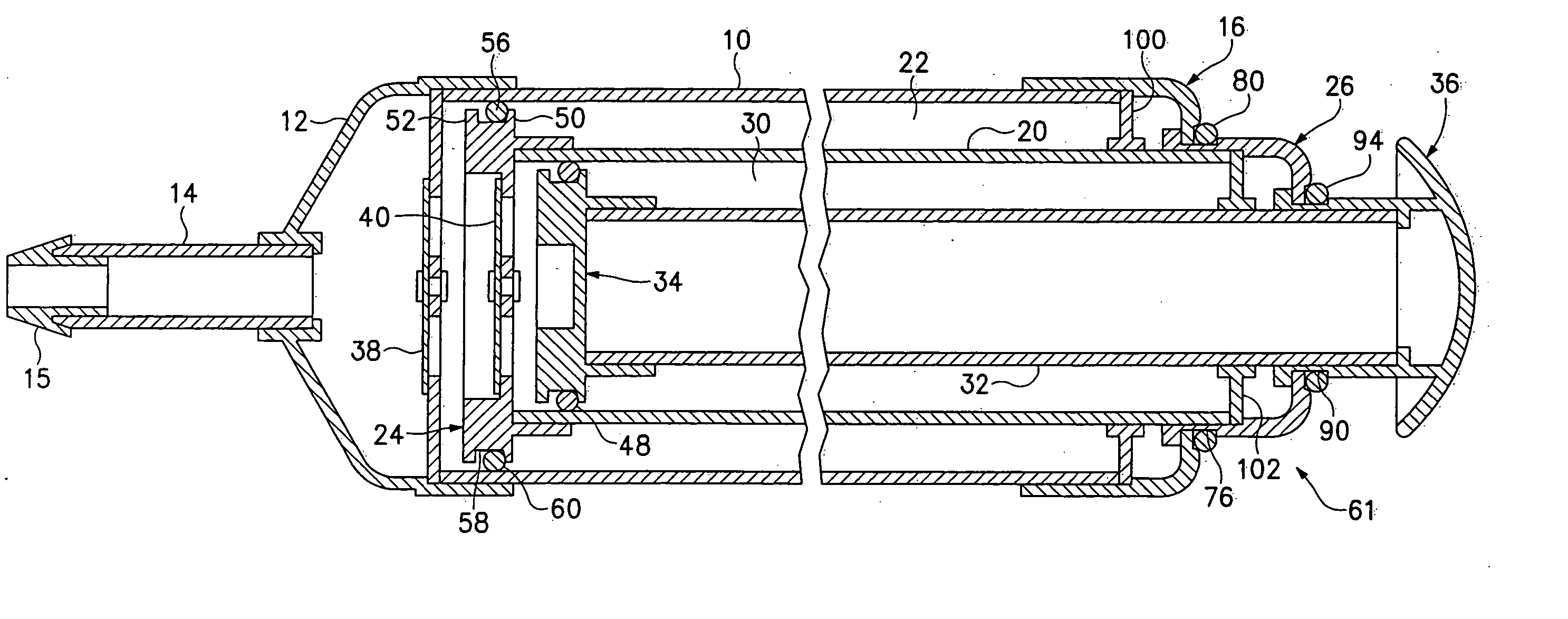
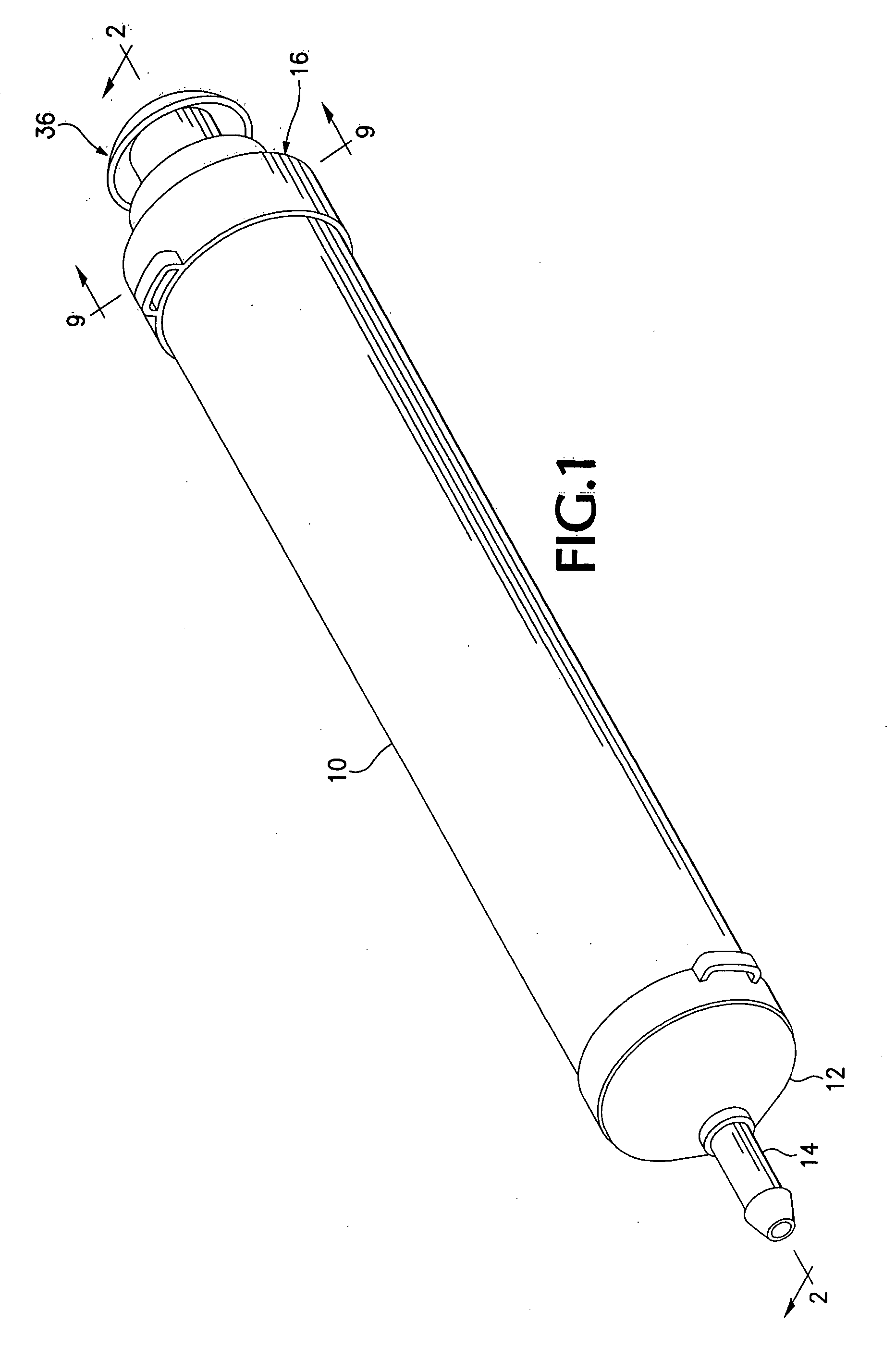
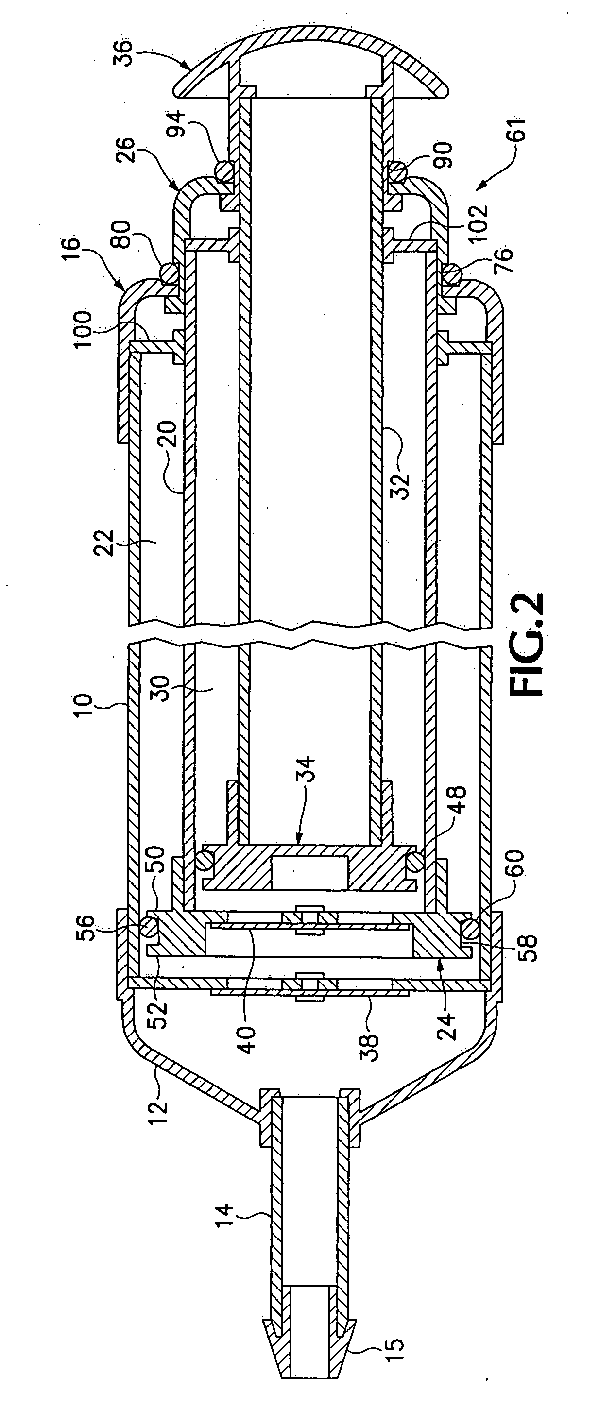
[0016] Referring now to FIGS. 1 and 2 of the drawings, a two-stage hand operated air pump includes an elongate tubular outer tube 10 which is open on each end. The outlet end of the outer tube 10 is covered by a funnel-shaped end cap 12 having an outlet 14 which is configured to fit into the air valve (not shown) of an inflatable device, such as a raft. A fitting 15 releasably attaches to the end of the outlet to allow the pump to be used with rafts having smaller air valves. The other end of the outer tube 10 is covered by a first cap 16 having an opening 18 located in it, FIG. 3. The outer tube 10 defines a cylindrical second chamber 22.

[0017] Slidably located concentrically in the outer tube is an inner tube 20 which has an outside diameter which is slightly less than the diameter of the opening 18 in the first cap 16. Located at one end of the inner tube 20 is a second piston 24 which moves in the second chamber 22 when the inner tube 20 is moved in and out of the pump. Located...


PUM


Abstract

A hand pump for inflating rafts or similar inflatables has a first piston with a relatively low pumping volume which is capable of pumping relatively small volumes of air into a raft as the raft becomes full and is approaching its maximum pressure, and a second piston with a larger pumping volume that can pump larger volumes of air into a raft when it is empty or only partially filled. Both pistons are operated with a single plunger. When the plunger is rotated in a first direction to a first position a locking mechanism allows it to operate only the first piston, and when the plunger is rotated in a second direction to a second position the locking mechanism allows it to operate only the second piston.

Description

BACKGROUND OF THE INVENTION [0001] The subject invention relates to a pump for inflating rafts and similar inflatable devices, and in particular to such a pump which can provide either a large volume of air per stroke for initially filling the inflatable device, or a smaller volume of air per stroke for topping off a substantially filled inflatable device when its internal pressure has increased. [0002] Many inflatable devices have to be filled or have air added to them at a remote location where only a hand-operated pump is available. Many inflatables, such as river rafts, contain a large volume of air. In order to fill them in a reasonable time with a hand pump the pump needs to deliver a relatively large volume of air with each stroke. However, as the raft approaches full inflation pressure, which is around 3 PSI, it becomes very difficult to operate a large volume hand pump. Thus, it is common to rely first on a high volume pump to initially fill the raft in the first instance, ...

Claims


Application Information

Patent Timeline
Patent Type & Authority Applications(United States)
IPC IPC(8): F01B1/02
CPCF04B3/003F04B49/18F04B33/00
Inventor KUTELLA, JAMES D.
Owner K PUMP
Why Eureka
Try Eureka