

Golf putter
- Summary
- Abstract
- Description
- Claims
- Application Information
AI Technical Summary
Benefits of technology
Problems solved by technology
Method used
Image

Examples
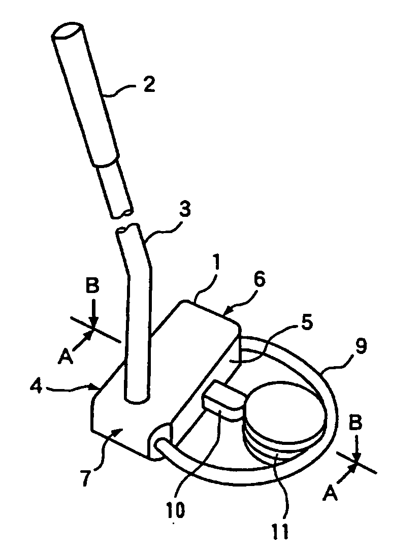
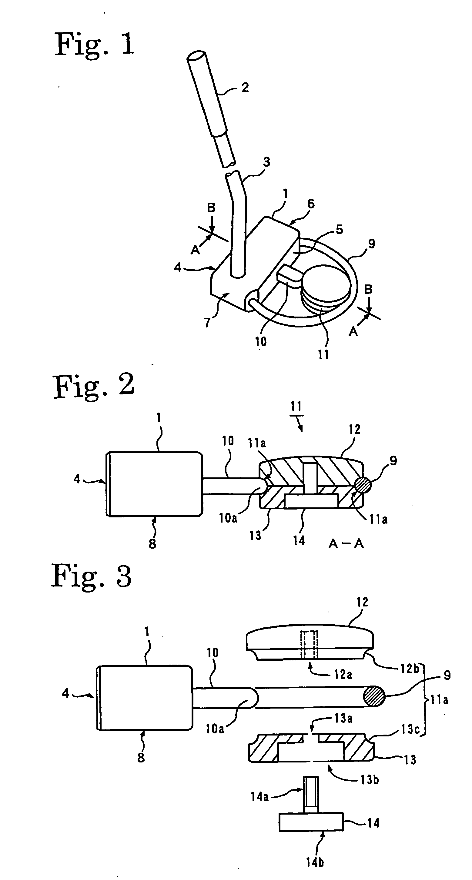
first embodiment
[0053]The present embodiment, being simple in structure compared with the first embodiment, can be manufactured easily and handled simply.
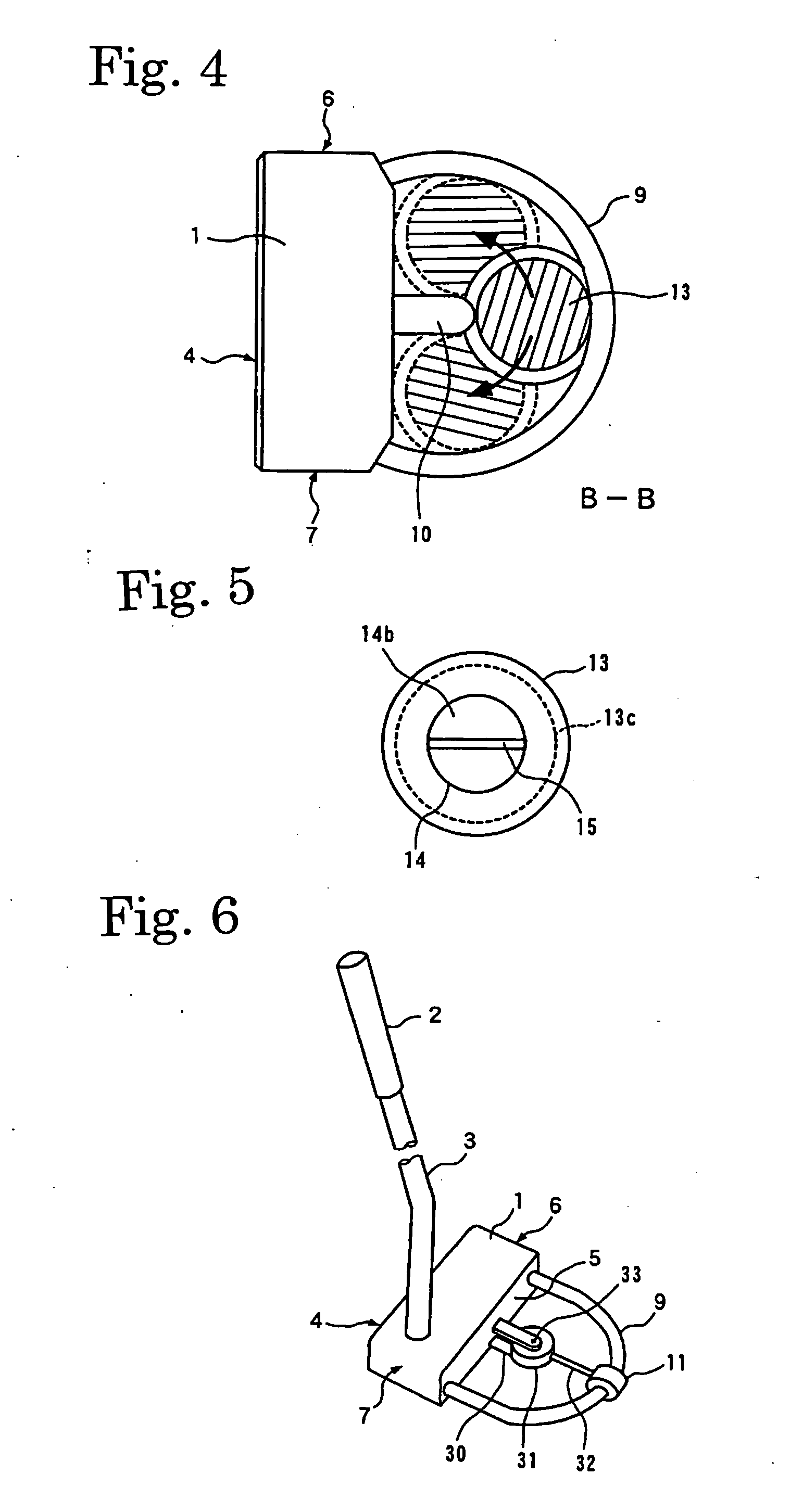
third embodiment
[0054]A putter according to the present invention is shown in FIG. 7, and the same parts as FIG. 1 are referred to with the same symbol.
second embodiment
[0055]In the present embodiment, the structure concerning the guide 9 and the weight 11 is basically similar to the second embodiment; however it is characterized by the absence of a cylinder 21 and a bar shape body 21 and by that weight 11 can move alone.
[0056]To this weight 11, a balancer 23 for making adjustments for the balance is attached in the radial direction of the guide 9.
[0057]The present embodiment, being simple in structure compared with the second embodiment, can be manufactured more easily and handled simply.
[0058]Now, the actual usage of embodiments of the putter according to the present invention described above shall be explained based on FIG. 8. FIG. 8 is a plane view showing a case of hitting a golf ball with the head.
[0059]It should be noted that the principle is same for the other embodiments, though an example of the first embodiment shall be described here.
[0060]In order to hit a golf ball 16 with the head 1 to drive the ball straight ahead, as shown in FIG. ...
PUM
 Abstract
Description
Claims
Application Information