Single prong in situ spreader

Inactive Publication Date: 2007-09-27
FALAHEE MARK H
View PDF1 Cites 6 Cited by
  • Summary
  • Abstract
  • Description
  • Claims
  • Application Information

AI Technical Summary

Problems solved by technology

However, in many instances, the pedicle heads are very close together, if not touching, making it impossible to use a double-pronged spreader in these situations.
The problem is usually that the top prong cannot pass between the converging heads, whether or not a rod has been used.
Moreover, when utilizing a distractor to spread open the disc space for TLIF or PLIF procedures, the close proximity of the heads makes engaging the distractor cumbersome, if not impossible.
As shown in FIG. 2, even if a double-pronged spreader can somehow be wedged into place between the screw heads, the upper prong of the spreader still interferes with the distractor.

Method used


Image

  • Single prong in situ spreader
  • Single prong in situ spreader

Examples


Embodiment Construction

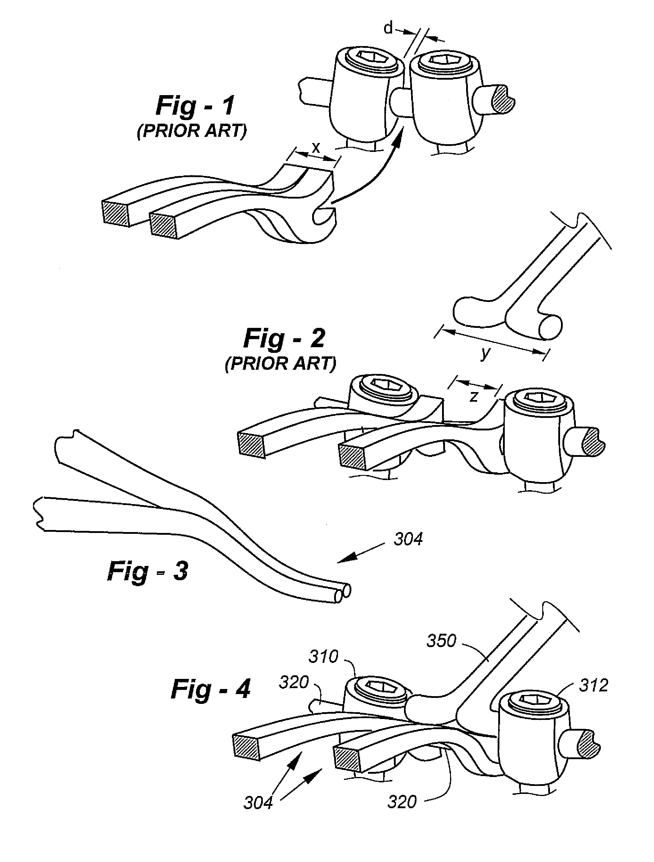
[0010]Having discussed the prior art with reference to FIGS. 1 and 2, the reader's attention is now turned to FIG. 3, which shows a single-pronged spreader according to this invention. The instrument has a proximal portion (not shown) with handles, the shape of which may be varied to include finger holes, and the like, with a distal portion including a pair of opposing prongs 304 having tapered ends.

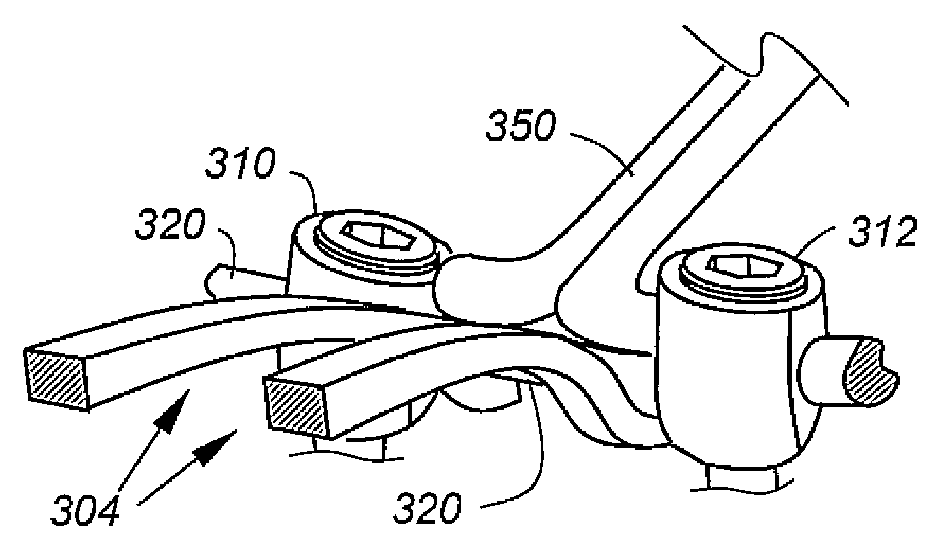
[0011]As shown in FIG. 4, this allows the prongs to be inserted between pedicle screw heads 310, 312, typically against the outer surfaces of the screw heads where they emerge from the bone surface. The tapered ends of the spreader are dimensioned to fit below the rod 320, if present. As can be seen in the figure, this allows the pedicle screws to be spread apart (with the rod loosened), allowing more room for the distractor 350 to be subsequently applied.


PUM


Abstract

Spinal instrumentation and methods are adapted for use with implanted pedicle screws having exposed heads with opposing surfaces between a bony surface and a rod-capturing through bore. The instrumentation includes a spreader having a proximal end and a distal end, the proximal end including a pair of handles and the distal end including a single pair prongs. The prongs of the spreader have tapered ends with opposing surfaces adapted to engage with the opposing surfaces of the exposed heads of the pedicle screws and spread them apart when pressure is applied to the handles. A method of spreading implanted pedicle screws having exposed heads, comprises the steps of inserting the prongs of the spreader between the opposing surfaces of the exposed pedicle screw heads, and spreading the exposed heads through the application of pressure to the handles of the spreader. The method may further including the step of applying a distractor over the prongs of the spreader when the exposed pedicle screw heads are moved apart.

Description

REFERENCE TO RELATED APPLICATION[0001]This application claims priority from U.S. Provisional Patent Application Ser. No. 60 / 785,219, filed on Mar. 23, 2006, the entire content of which is incorporated herein by reference.FIELD OF THE INVENTION[0002]This invention relates generally to spinal surgery and, in particular, to an in situ spreader utilized to move apart adjacent pedicle screw heads, with or without a rod.BACKGROUND OF THE INVENTION[0003]As shown in FIG. 1, current surgical spreaders are double-pronged, as they are designed to engage upper and lower surfaces of a rod between the pedicle heads to facilitate spreading. However, in many instances, the pedicle heads are very close together, if not touching, making it impossible to use a double-pronged spreader in these situations. The problem is usually that the top prong cannot pass between the converging heads, whether or not a rod has been used. Moreover, when utilizing a distractor to spread open the disc space for TLIF or ...

Claims


Application Information

Patent Timeline
IPC IPC(8): A61F2/30
CPCA61B2017/0256A61B17/7079
Inventor FALAHEE, MARK H.
Owner FALAHEE MARK H
Why Eureka
Try Eureka