Side airbag apparatus

a side airbag and apparatus technology, applied in the direction of pedestrian/occupant safety arrangement, vehicular safety arrangments, vehicle components, etc., can solve the problems that the above-mentioned disadvantage might occur in the same manner, and achieve the effect of stable gas flow through the gap and increasing the internal pressure of the upper chamber later

Inactive Publication Date: 2007-10-04
TOYODA GOSEI CO LTD
View PDF9 Cites 40 Cited by
  • Summary
  • Abstract
  • Description
  • Claims
  • Application Information

AI Technical Summary

Benefits of technology

[0010]Therefore, at the initial stage of inflation and deployment of the airbag, most of the gas blown out of the gas port flows into one of the chambers, and the gas that has flowed into the one of the chambers is restricted from flowing into the other chamber by the partition. Thereafter, when the internal pressure of the one of the chambers is increased, the amount of gas that flows from the one of the chambers to the other chamber through the gap between the inflator and the inner tube gradually increases, thus increasing the internal pressure of the upper chamber later. The flow passage area of gas through the gap between the inflator and the inner tube is maintained substantially constant from the initial stage to the completion of inflation and deployment of the airbag. Thus, although the flow rate of gas changes as described above, the state of gas flow through the gap is stable. Since the flow of gas into the chambers is controlled as described above during inflation and deployment of the airbag, the internal pressures of the chambers change in a stable manner. As a result, the maximum internal pressure of the one of the chambers is reliably higher than that of the other chamber. Thus, a clear difference is made between the maximum internal pressures. Moreover, by a simple design modification in which the diameter of the inner tube is changed to adjust, as required, the size of the gap formed between the inner tube and the inflator during inflation and deployment of the airbag, the difference between the maximum internal pressures of the chambers is adjusted with a considerable amount of freedom.

Problems solved by technology

However, in this case also, the above-mentioned disadvantage might occur in the same manner.

Method used


Image

  • Side airbag apparatus
  • Side airbag apparatus
  • Side airbag apparatus

Examples


Embodiment Construction

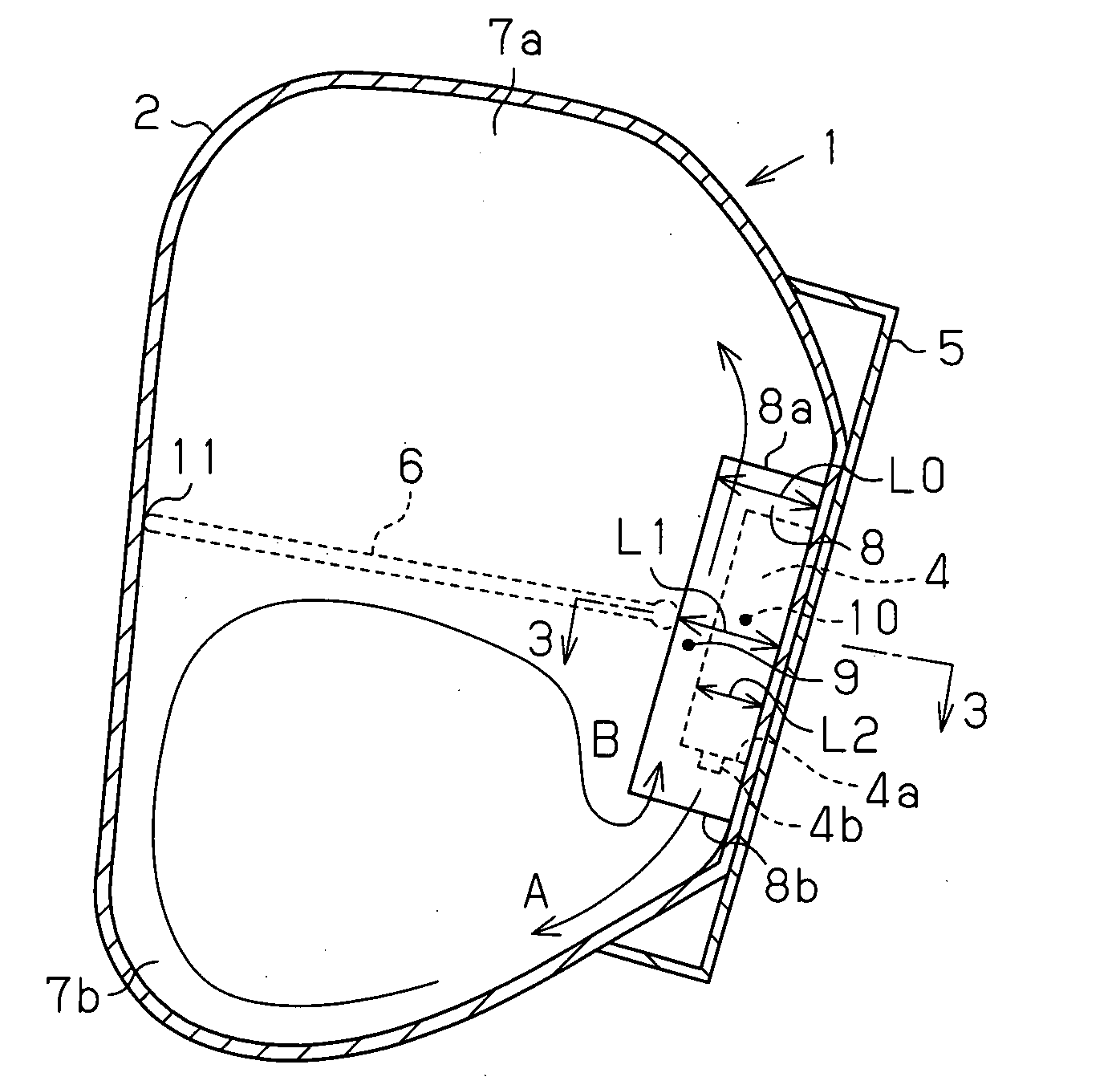
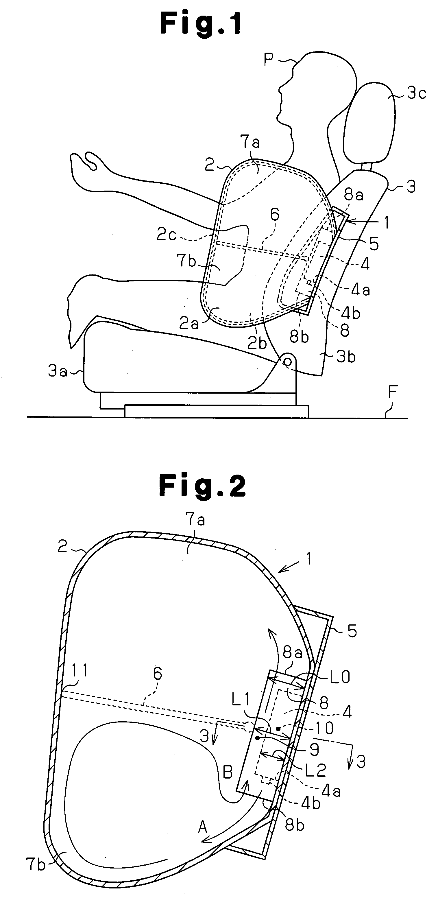
[0020]A side airbag apparatus 1 according to one embodiment of the present invention will now be described with reference to FIGS. 1 to 5.

[0021]As shown in FIG. 1, a seat 3 is arranged on a floor F of a passenger compartment. The seat 3 is a single front seat located on the left side of the passenger compartment, and includes a seat portion 3a, a backrest 3b, and a headrest 3c.

[0022]The vehicle is provided with the side airbag apparatus 1 as one of occupant protection devices. The side airbag apparatus 1 includes a columnar inflator 4, which blows out gas, and an airbag 2, which is inflated and deployed in the passenger compartment by the gas blown out from the inflator 4.

[0023]The airbag 2 is accommodated in a case 5 and arranged in the backrest 3b of the seat 3. Although not shown in the drawings, a side airbag apparatus is provided for a seat on the right side of the passenger compartment in the same manner.

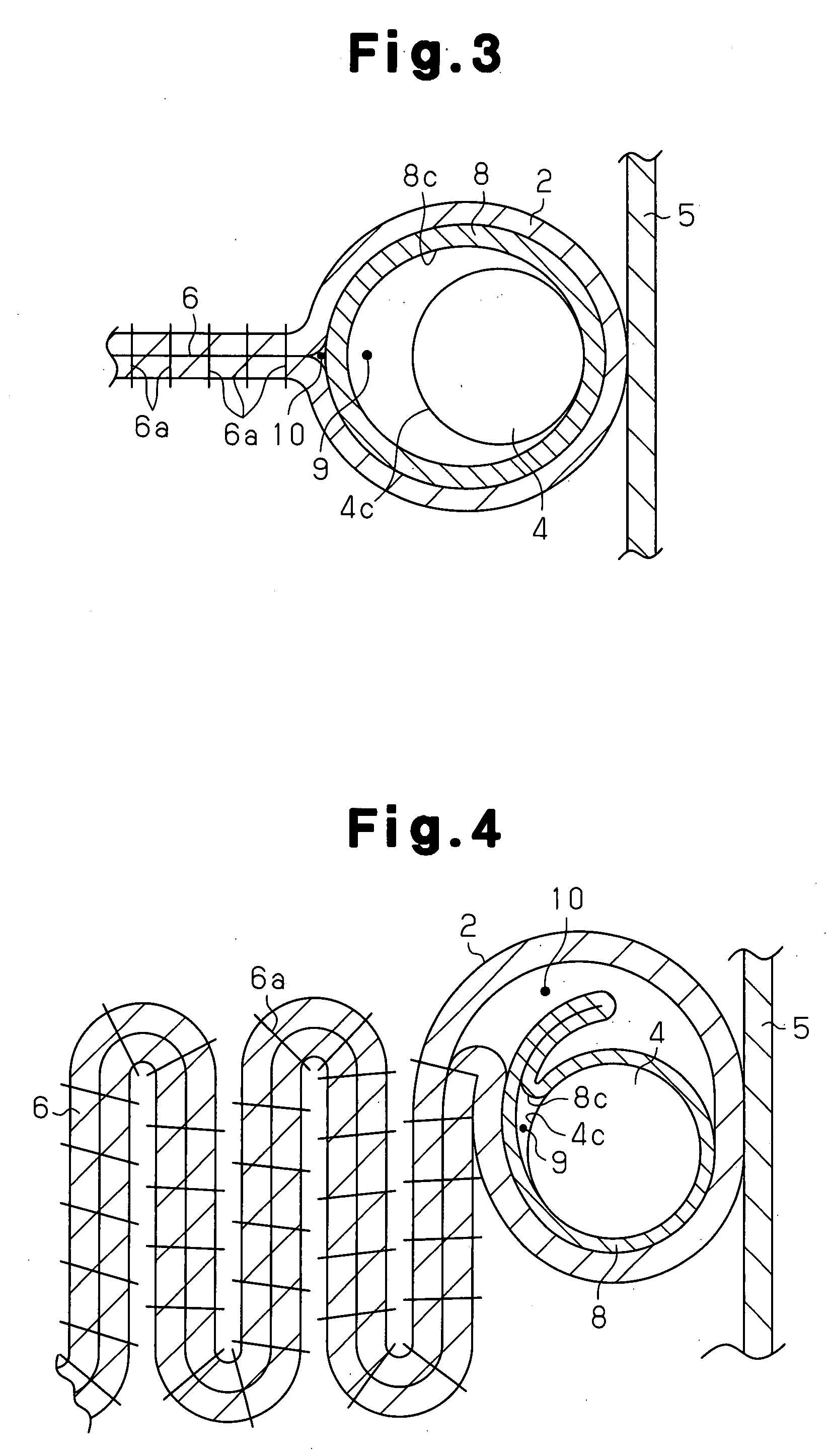
[0024]As shown in FIGS. 1 and 2, the airbag 2 is formed into a bag shape...


PUM


Abstract

An airbag includes a seam, which divides the airbag into an upper chamber and a lower chamber. An inner tube is provided inside the airbag such that openings are each located in one of the chambers. An inflator is inserted in the inner tube such that gas blown out from a gas port is oriented toward the lower chamber. A gap formed between an outer circumferential surface of the inflator and an inner circumferential surface of the inner tube during inflation and deployment of the airbag connects the upper chamber to the lower chamber.

Description

BACKGROUND OF THE INVENTION[0001]The present invention relates to a side airbag apparatus that inflates and deploys an airbag between the side of a vehicle and an occupant.[0002]As an occupant protection device of a vehicle, for example, a side airbag apparatus disclosed in Japanese Laid-Open Patent Publication No. 2005-225351 has been proposed. The side airbag apparatus inflates and deploys an airbag between the side of a vehicle and an occupant seated in a seat when great impact force is applied from the lateral direction of a vehicle, such as in the case of side impact. FIGS. 6 and 7 illustrate the configuration of a conventional side airbag apparatus including that of the above publication.[0003]As shown in FIGS. 6 and 7, the inside of an airbag 102 is divided into an upper chamber 107a and a lower chamber 107b by a tether 106. The chambers 107a, 107b are connected to each other by a communication section 110 (a front communication section 110a and a rear communication section 1...

Claims


Application Information

Patent Timeline
Patent Type & Authority Applications(United States)
IPC IPC(8): B60R21/26B60R21/233B60R21/207B60R21/20B60R21/16
CPCB60R21/23138B60R2021/23316B60R2021/23146B60R21/2346
Inventor YAMAMURA, DAISUKE
Owner TOYODA GOSEI CO LTD
Why Eureka
Try Eureka