

Fuel-cell power generation system for supplying hydrogen by hydrolyzing magnesium hydride
A fuel cell and magnesium hydride technology, applied in solid electrolyte fuel cells, fuel cells, fuel cell additives, etc., can solve the problem of high cost, achieve the effect of large hydrogen release, low density, and reduced application cost
- Summary
- Abstract
- Description
- Claims
- Application Information
AI Technical Summary
Problems solved by technology
Method used
Image

Examples
Embodiment 1
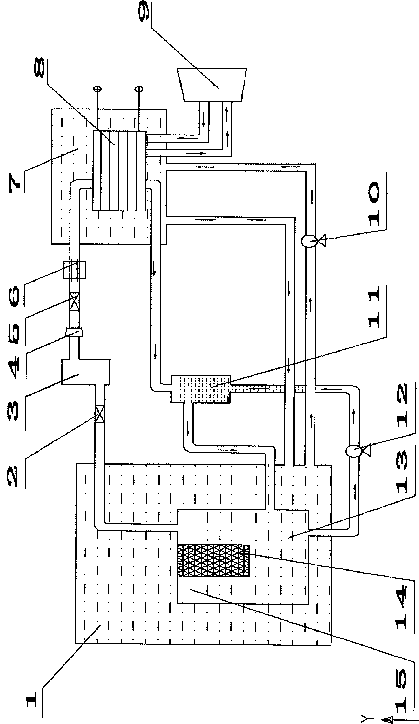
[0035] Close the switch of the fuel cell stack, close the hydrogen pressure regulator (4), the hydrogen partial pressure valve (5), and close the hydrolysis reactor filter (12). The pressure in the hydrogen storage tank (3) is constantly increasing, and the water in the hydrolysis reactor (13) is constantly pressed out, and enters in the water storage tank (11), until the MgH in the hydrolysis reactor 2 The briquettes are completely separated from the water. Close the total hydrogen pressure valve (2). Close the water bath circulation pump (10). The device stops working.
Embodiment 2
[0037] Open the hydrogen total pressure valve (2), the hydrogen pressure regulator (4), the hydrogen partial pressure valve (5), and open the fuel cell stack switch. Turn on the water bath circulating water pump (10). Along with the consumption of hydrogen, the pressure in the hydrogen storage tank (3) decreases continuously, and the water in the water storage tank (11) continuously flows back in the hydrolysis reactor (13) until the liquid level is stable. Open the hydrolysis reactor filter (12). The device works stably.
Embodiment 3
[0039] When the device is working stably, the fuel cell is in a low power state, the hydrogen production rate exceeds the fuel cell consumption rate, the pressure in the hydrogen storage tank (3) is continuously increasing, and the water in the hydrolysis reactor (13) is continuously pressed out and enters the water storage In the tank (11), until the MgH in the hydrolysis reactor 2 The briquette is completely separated from the water, and the hydrolysis reaction stops. Realized automatic shutdown of hydrolysis reaction during work.
[0040] Along with the consumption of hydrogen, the pressure in the hydrogen storage tank (3) constantly reduces, and the water in the water storage tank (11) continuously flows back in the hydrolysis reactor (13), and the MgH in the hydrolysis reactor 2 The briquettes come into contact with water and the hydrolysis reaction starts. The automatic opening of the hydrolysis reaction in the work is realized.
PUM
 Abstract
Description
Claims
Application Information