Endoskeletal transformer tank

Inactive Publication Date: 2011-11-10
THOMPSON ROBERT SAMUEL
View PDF9 Cites 20 Cited by
  • Summary
  • Abstract
  • Description
  • Claims
  • Application Information

AI Technical Summary

Benefits of technology

[0026]In another embodiment, the present invention provides a transformer tank including a tank defining a rectangular cube shape having opposing tank walls and junctions between adjacent tank walls being intermediate walls defining an obtuse angle with respect to each of their respective adjacent tank walls such that the tank is free from perpendicular wall intersections, a transformer electrical core and coils immersed in a predetermined volume of internal fluid housed within the tank, and inte

Problems solved by technology

While the pressure relief device and expansion tank are typically able to accommodate minor and/or gradual increases in internal pressure, rapid increases in internal pressure resulting from internal fau

Method used


Image

  • Endoskeletal transformer tank
  • Endoskeletal transformer tank
  • Endoskeletal transformer tank

Examples


Embodiment Construction

[0038]The present invention will now be described more fully hereinafter with reference to the accompanying drawings in which exemplary embodiments of the invention are shown. However, the invention may be embodied in many different forms and should not be construed as limited to the representative embodiments set forth herein. The exemplary embodiments are provided so that this disclosure will be both thorough and complete, and will fully convey the scope of the invention and enable one of ordinary skill in the art to make, use and practice the invention.

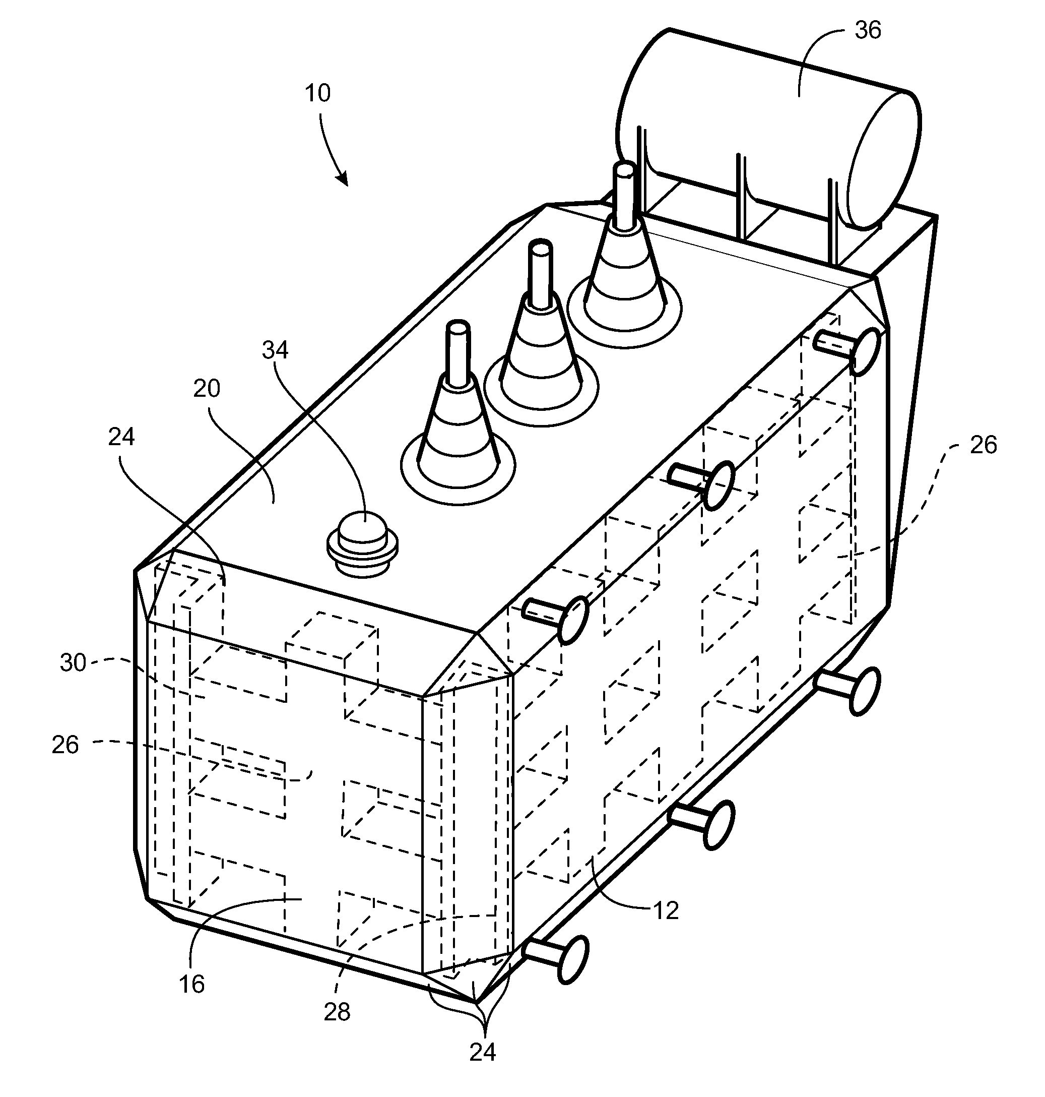
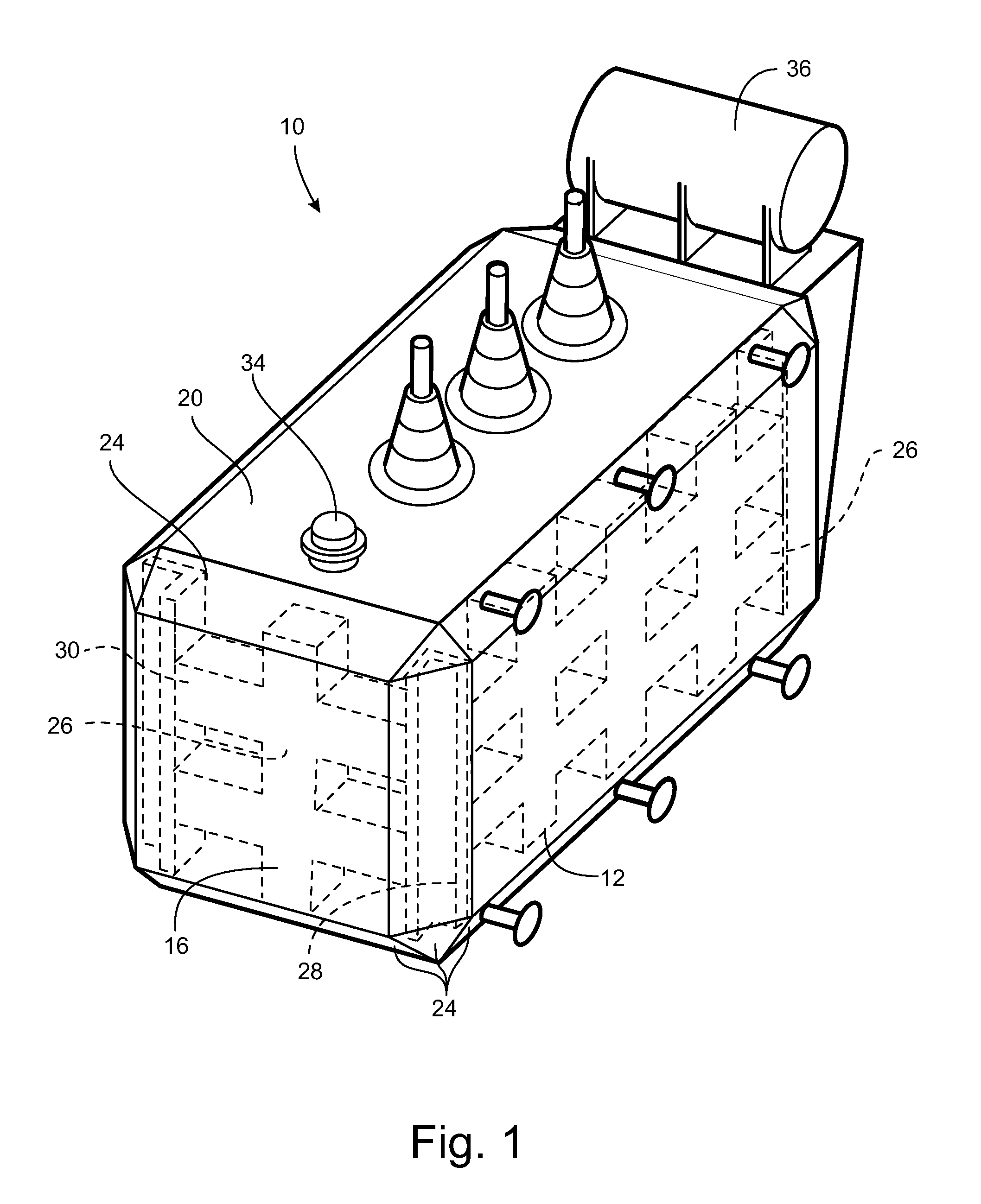
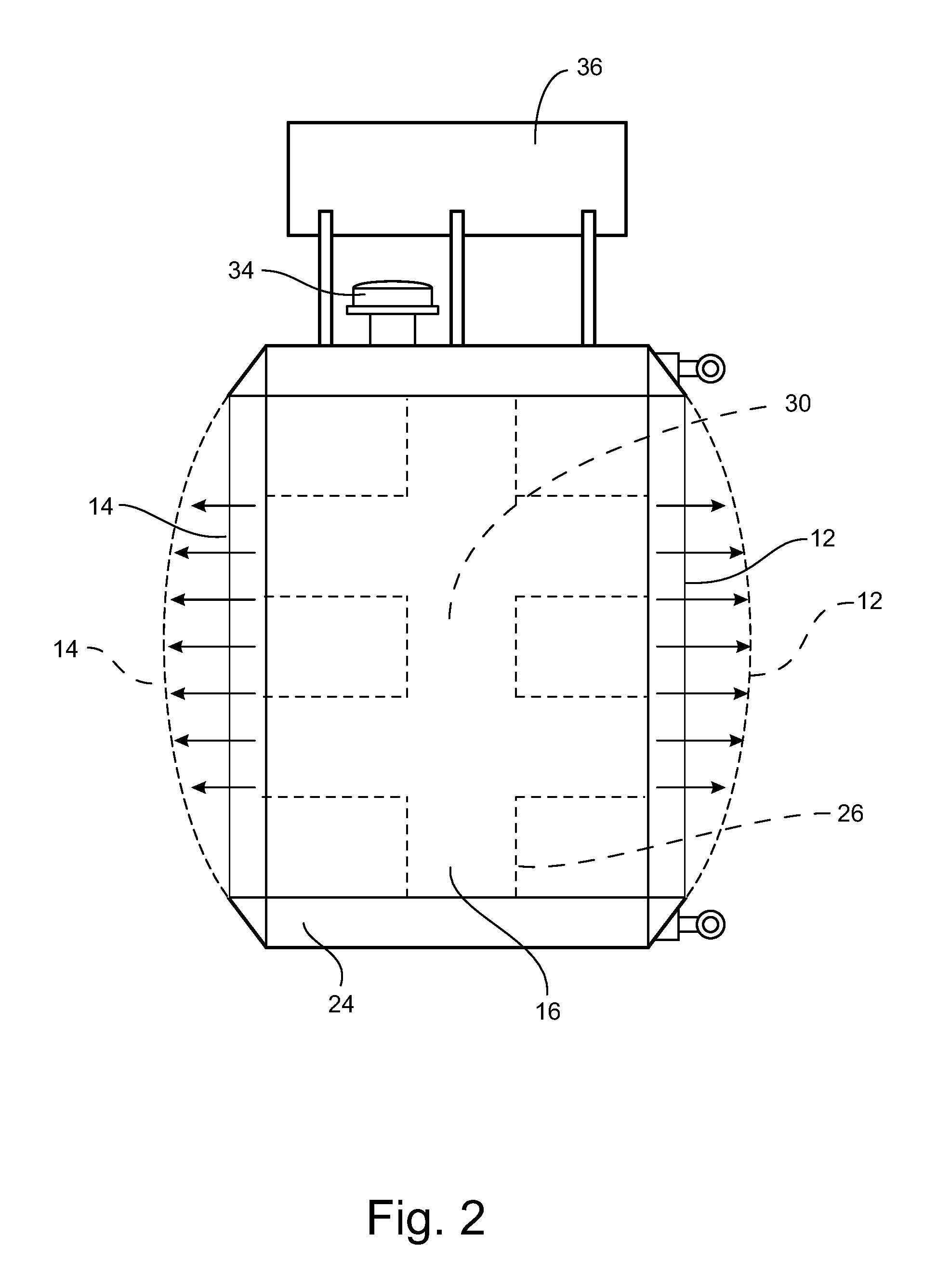
[0039]Referring to the figures, a transformer tank in accordance with an embodiment of the invention is shown generally at reference numeral 10. Transformer tank 10 is of the basic type known to those skilled in the art for housing a transformer electrical core and coils immersed in transformer oil, for example, highly refined mineral oils, silicone-based oils and fluorinated hydrocarbons, among others, referred to herein collectiv...


PUM


Abstract

A transformer tank having opposing walls and junctions between adjacent tank walls being intermediate walls defining obtuse angles with respect to each of their respective adjacent tank walls such that the tank is free from perpendicular wall intersections. Internal framework is disposed within the tank for preventing inward wall deflections and is anchored to the intermediate walls and is substantially free from attachment to the opposing walls. The tank undergoes volumetric expansion in response to increases in internal positive pressure to avoid tank rupture.

Description

TECHNICAL FIELD AND BACKGROUND OF THE INVENTION[0001]1. Field of the Invention[0002]The present invention relates generally to the field of transformer tank construction, and more particularly, to a rupture-resistant transformer tank designed to resist inward deflection of the tank walls in response to negative internal pressures while allowing outward deflection of the tank walls in response to internal fault pressures, such as from internal gaseous explosions, electrical faults and overcurrent conditions.[0003]2. Background of the Invention[0004]Transformer tanks of the type relating to the present invention are typically designed to house a transformer electrical core and coils immersed in transformer oil that both cools and insulates the windings. Conventional tank designs typically include a rectangular cube having a fixed volume that houses the power transformer and mitigates increases in pressure by way of a pressure relief device and by an externally attached expansion tank ...

Claims


Application Information

Patent Timeline
IPC IPC(8): H01F27/02B65D1/46B65D1/42
CPCH01F27/02
Inventor THOMPSON, ROBERT SAMUEL
Owner THOMPSON ROBERT SAMUEL
Why Eureka
Try Eureka