Breather structure for internal combustion engine

a technology for internal combustion engines and breather, which is applied in the direction of combustion engines, gearing details, belts/chains/gearings, etc., can solve the problems of making the impact of the fluctuation in the pressure in the crank chamber great, and achieve the effect of reducing the fluctuation of the pressure inside the auxiliary apparatus chamber, and reducing the fluctuation of the pressur

Inactive Publication Date: 2008-01-31
HONDA MOTOR CO LTD
View PDF5 Cites 22 Cited by
  • Summary
  • Abstract
  • Description
  • Claims
  • Application Information

AI Technical Summary

Benefits of technology

[0011] In the breather structure for internal combustion engine, configured as described above, an increased internal pressure in the crank chamber is lowered once in the small chamber, and then is lowered further in the auxiliary apparatus chamber which has a large capacity, and in which the clutch mechanism is housed. As has just been described, the crank chamber does not directly communicate to the auxiliary apparatus chamber, so that the fluctuation in pressure inside the auxiliary apparatus chamber can be made smaller. Additionally, this auxiliary apparatus chamber communicates to the breather chamber, while the breather chamber communicates to the outside of the housing through the external communication port. The small chamber provided as has just been described makes the mitigation of the pressure fluctuation in the auxiliary apparatus chamber so effective that a smaller breather chamber than that of the conventional breather structure can have a sufficient breathing effect. As a result, the internal combustion engine as a whole can be made smaller in size.
[0012] Additionally, in a configuration with shaft members of the power transmission system being housed in the crank chamber, a transmission mechanism, such as gears, is provided around the shaft members. Such a configuration tends to produce a dead space in an outer peripheral portion of the transmission mechanism. The breather chamber with a smaller capacity and the smaller chamber can be provided inside the case by making use of this dead space. Such effective use of a space makes it unnecessary to provide special members dedicated to form the small chamber and the breather chamber. This simplifies the housing structure of the power transmission system and of the internal combustion engine. As a result, an internal combustion engine produced at a lower cost can be provided.
[0013] At this time, when the gears constituting the transmission mechanism of the power transmission system are housed in the crank chamber, an area, overlapping the gears when viewed from a side, is formed in the auxiliary apparatus chamber, which is formed inside the

Problems solved by technology

Such a breather structure, however, makes the impact of the fluctuation in the pressure in t

Method used


Image

  • Breather structure for internal combustion engine
  • Breather structure for internal combustion engine
  • Breather structure for internal combustion engine

Examples


Embodiment Construction

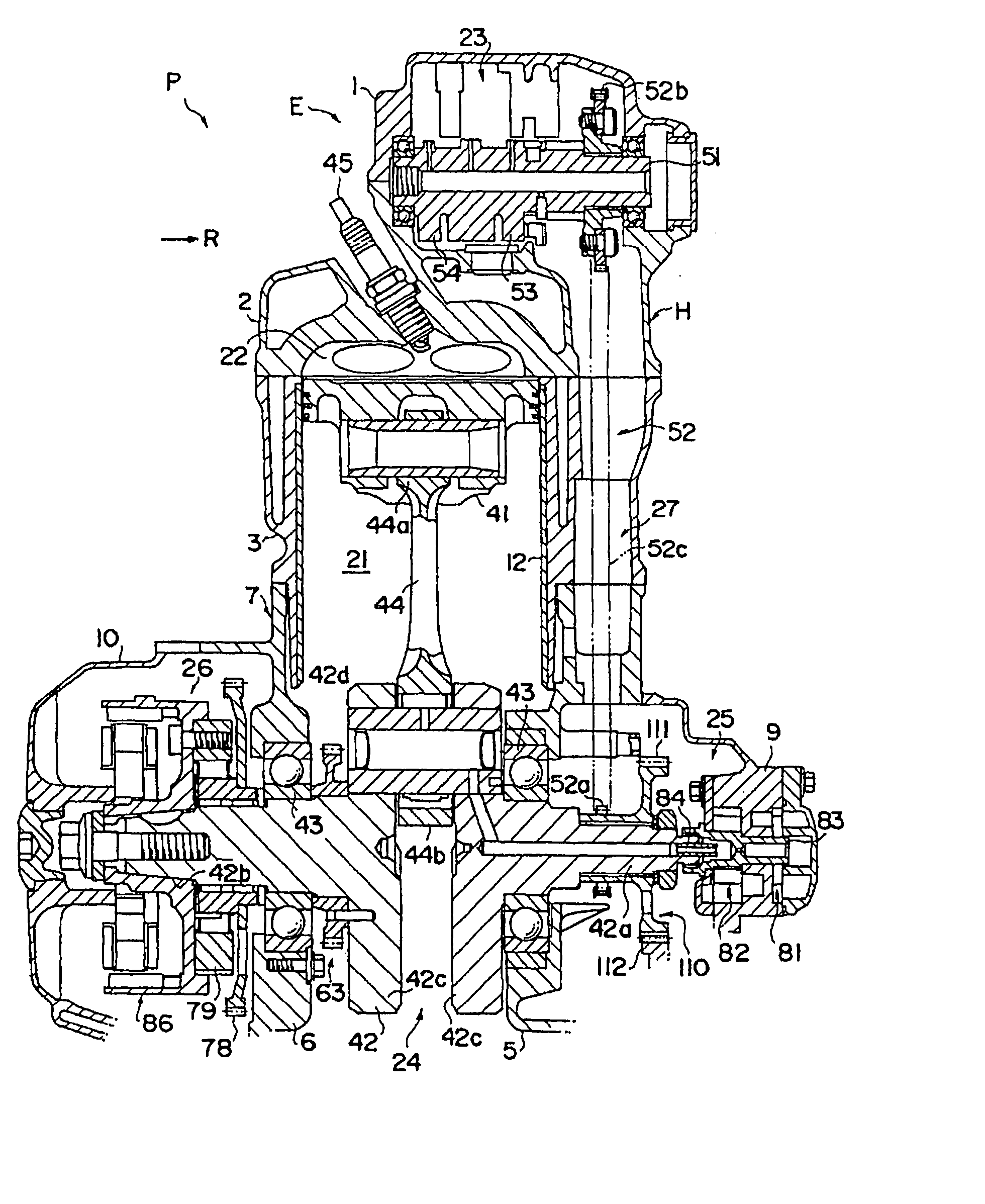
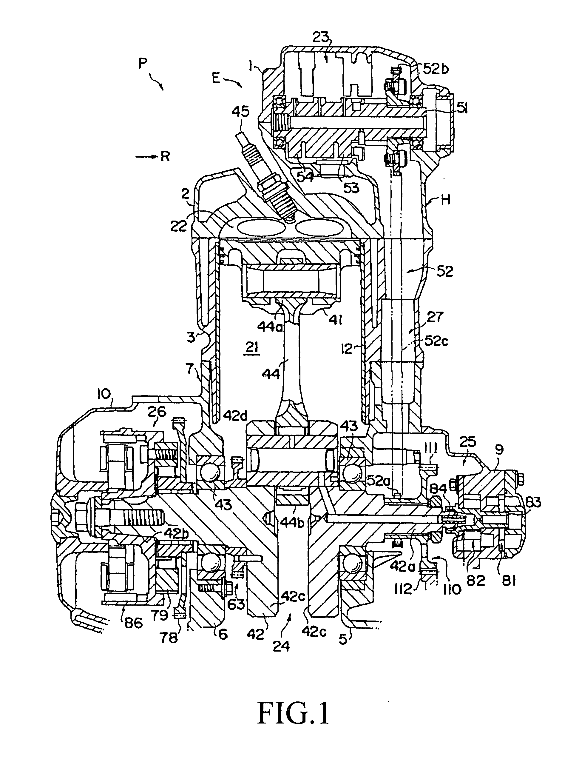
[0026]FIG. 1 to FIG. 5 illustrate a power unit P of a saddle-ride type vehicle equipped with a breather structure for internal combustion engine according to the present invention. In the figures, an arrow U indicates the upward direction; an arrow F, the forward direction; and an arrow R, the rightward direction. The directions indicated by these arrows correspond to the directions from the viewpoint of the driver of the saddle-ride type vehicle. Examples of the saddle-ride type vehicle include a motorcycle and an all-terrain buggy.

[0027] The power unit P includes components in and outside of a housing H. The housing H is formed by assembling a head cover 1, a cylinder head 2, a cylinder block 3 and a crankcase 4 into one. Specifically, the cylinder head 2 is joined to the top of the cylinder block 3. The head cover 1 is joined to the cylinder head 2 so as to cover the cylinder head 2. The crankcase 4 is joined to the bottom of the cylinder block 3.

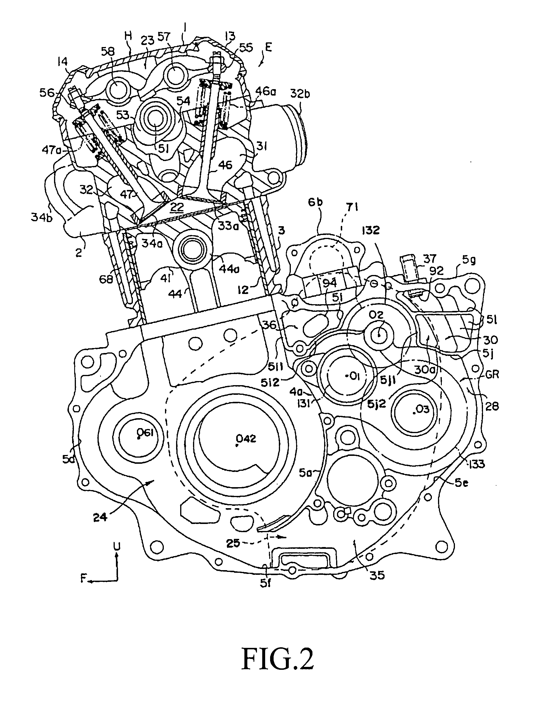
[0028]FIG. 2 and FIGS. 6 to 8 s...


PUM


Abstract

A breather structure for internal combustion engine, the structure making a breather chamber smaller and thus making an internal combustion engine as a whole smaller. A breather chamber and a small chamber are formed. The breather chamber includes a first side face cover. The first side face cover is joined to a case to cover a first one of the right and left side faces of the case. Inside the first side face cover, an auxiliary apparatus chamber is formed. The auxiliary apparatus chamber houses a clutch mechanism connecting or disconnecting the power transmission route. Additionally, formed inside a housing are an external communication port communicating to the outside of the housing, and the small chamber communicating to a crank chamber and to the auxiliary apparatus chamber. Moreover, the auxiliary apparatus chamber communicates to the breather chamber.

Description

CROSS-REFERENCE TO RELATED APPLICATION [0001] The present application claims priority under 35 U.S.C. §119 to Japanese Patent Application No. 2006-094412, filed Mar. 30, 2006, the entire contents of which are hereby incorporated by reference. BACKGROUND OF THE INVENTION [0002] 1. Field of the Invention [0003] The present invention relates to a breather structure for an internal combustion engine with a cylinder block and a case joined to the cylinder block. The cylinder block has a cylinder bore formed therein, and a piston, which is disposed in the cylinder bore by being inserted thereinto, and which can reciprocally travel freely in the cylinder bore. Meanwhile, the case has a crank chamber communicating to the cylinder bore. A crankshaft is housed in the crank chamber, while the crankshaft rotates in conjunction with the piston. [0004] 2. Description of Background Art [0005] In such an internal combustion engine, the internal pressure of the crank chamber, which communicates to t...

Claims


Application Information

Patent Timeline
IPC IPC(8): F02B77/00F01M13/00F01M13/04F02B61/06F16H57/027
CPCF01M13/04F02B61/02F01M2013/0461
Inventor KEYAKI, SHINICHIRONISHI, TORUIINO, KAZUAKISUMI, HIROMI
Owner HONDA MOTOR CO LTD
Why Eureka
Try Eureka