Hinged closure moulded in closed position

Inactive Publication Date: 2006-07-27
CREANOVA
View PDF17 Cites 25 Cited by
  • Summary
  • Abstract
  • Description
  • Claims
  • Application Information

AI Technical Summary

Benefits of technology

[0010] Hinged closures moulded in a closed position in general comprise a ring shaped lower part (body) and a cap like upper part (lid) which is connected by a hinge to the lower part. The cap like upper part in general does incorporate a built in sealing device and/or a separate sealing mean. The ring like lower part in general does comprise holding means which are suitable to fix the closure on a s corresponding neck of a bottle. The lower and the upper part of the closure

Problems solved by technology

This aspect has to be considered in mould design, because closures having a

Method used


Image

  • Hinged closure moulded in closed position
  • Hinged closure moulded in closed position
  • Hinged closure moulded in closed position

Examples


Embodiment Construction

[0033] A better understanding of the present invention may be obtained by the present detailed description which, when examined in connection the accompanying drawings sets forth preferred embodiments of the inventions described herein. It should be understood that corresponding elements in the various figures are generally identified with corresponding reference numbers.

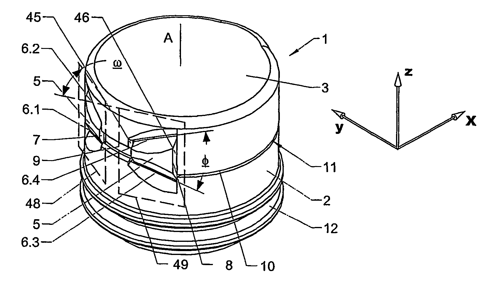
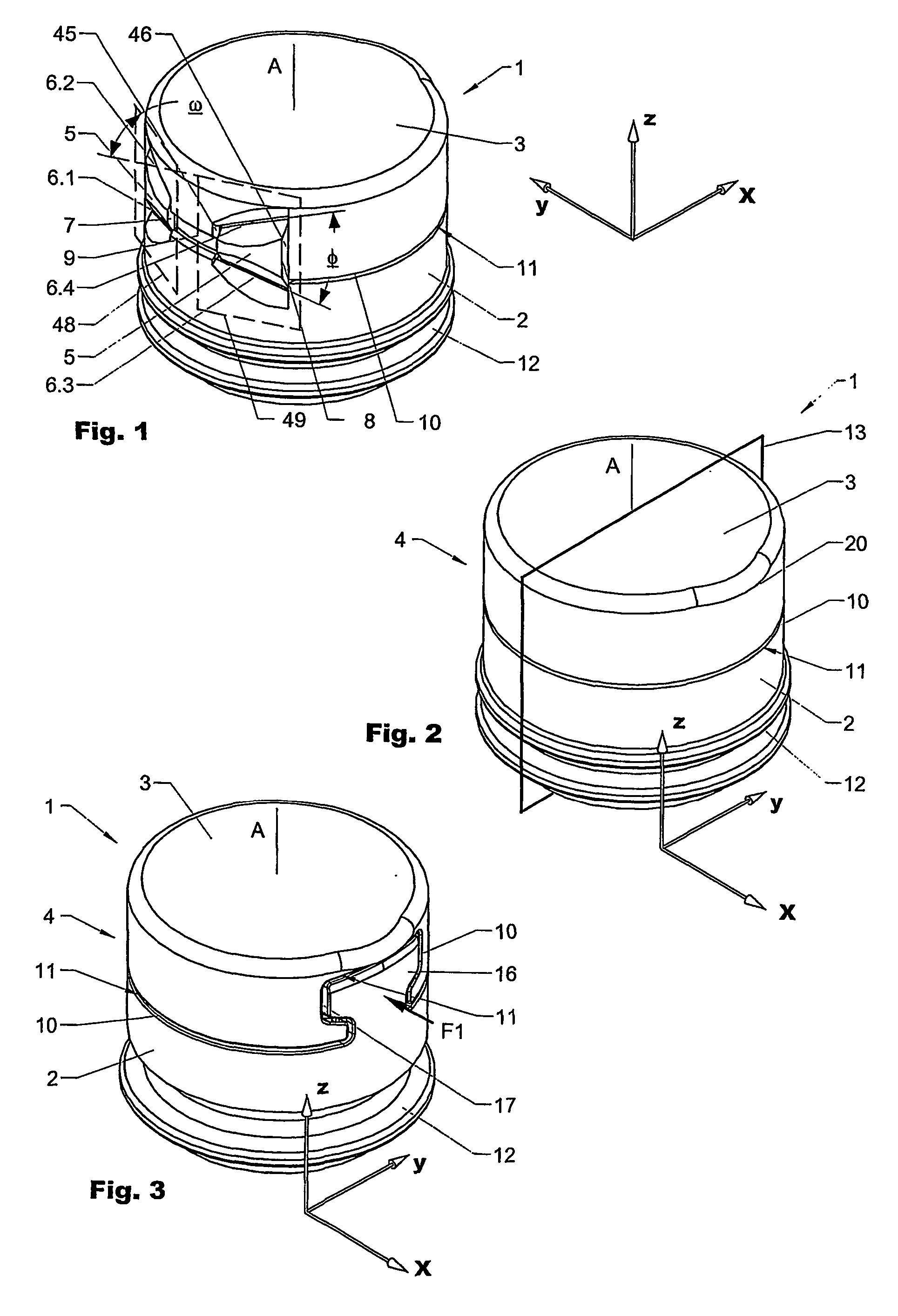
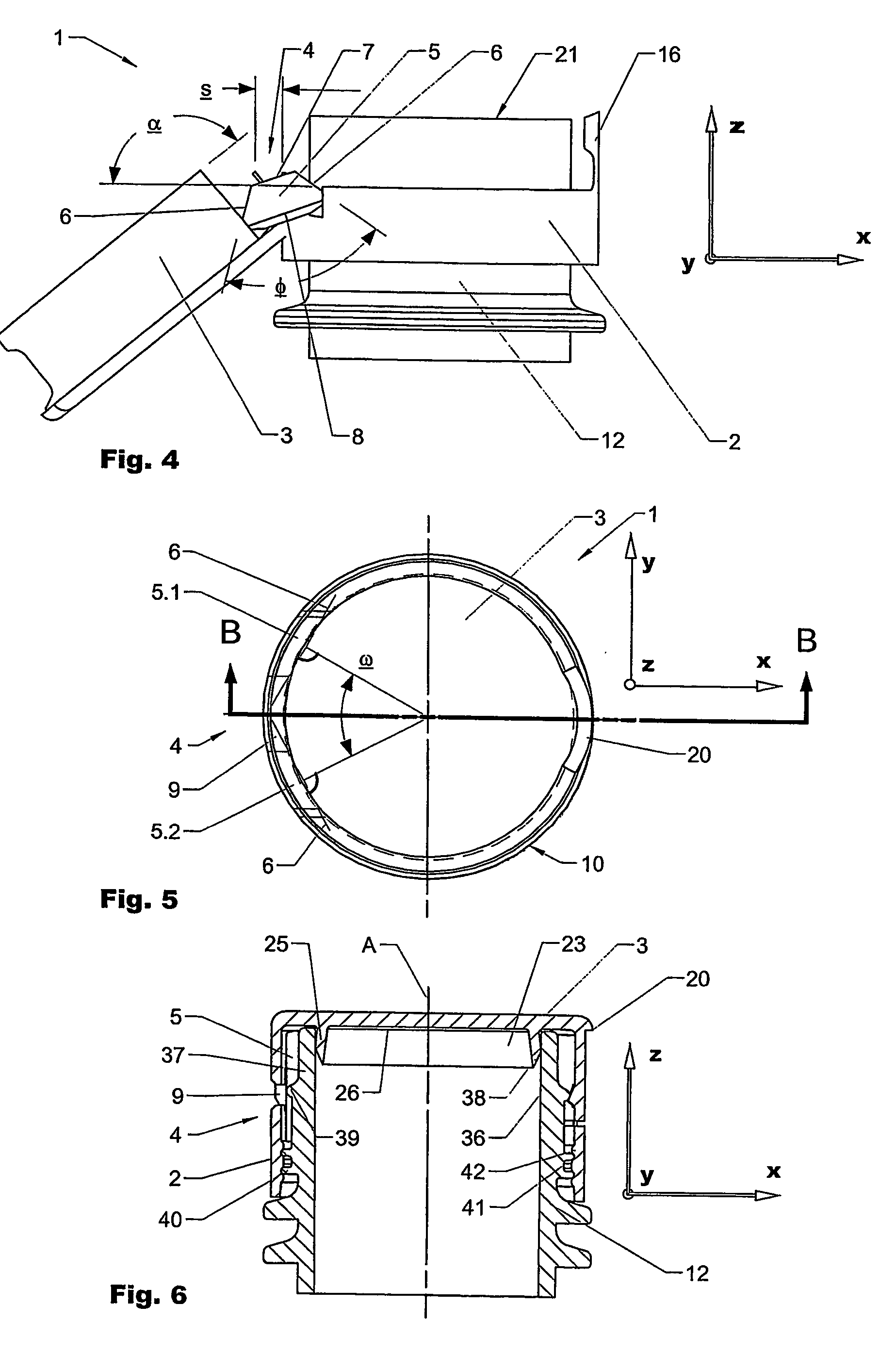
[0034]FIG. 1 illustrates a hinged closure 1 according to the present invention moulded in closed position in a perspective view from the back. The closure 1 comprises a ring shaped lower part 2 (body) and a cap like upper part 3 (lid) which are interconnected by a snap hinge 4. In contrast to most of the hinges known from the state of the art the snap hinge 4 does not have a main hinge connection between the body 2 and the lid 3. The snap hinge 4 comprises a first and a second trapezoid element 5, of which each is connected to the body 2 and the lid 3 by a first and a second film hinge element 6.1, 6.2, respectivel...


PUM


Abstract

The invention is directed to a closure moulded in closed position. The closure comprises a body and a lid, which are separated by a circumferential gap. A snap hinged comprising two trapezoid elements, which are connected each by film hinges to the body and the lid, causes a snap action while opening or closing the closure. The closure offers opening angles in the range of 220°.

Description

FIELD OF THE INVENTION [0001] The present invention is directed to a hinged closure moulded in closed position and a container suitable to be used with the hinged closure according to the preamble of the independent claim. BACKGROUND OF THE INVENTION [0002] From the state of the art screw caps e.g. drinking bottles made of polyethylene (PET) and bottles made of glass are know. One disadvantage of these closures is that a lot of physical strength is necessary to open and to close them. Besides this, the known screw cap closures are in general difficult to mould due to the thread on the inside which often causes problems in demoulding. A further disadvantage is that the screw caps can not be operated single handed and after opening the cap has to be held separately. [0003] From EP 1 147 054 a hinged closure with a hinge moulded in closed position is known. Although is this closure shows significant improvements over the closures known from the state of the art, due to the arrangement ...

Claims


Application Information

Patent Timeline
IPC IPC(8): B65D39/00B65D53/00B65D51/04B65D47/08
CPCB65D41/16B65D47/0809B65D2101/00B65D2401/00
Inventor LAGLER, LOUIS
Owner CREANOVA
Why Eureka
Try Eureka