
Magnetically-levitated telescopic land indicator

a telescopic indicator and magnetic technology, applied in the field of land indicators, can solve the problems of reducing so as to prevent the reflection unit from falling out, prolong the life of the land indicator, and avoid elastic fatigue

Inactive Publication Date: 2007-10-04
CHIANG TSAI JUNG
View PDF2 Cites 3 Cited by
  • Summary
  • Abstract
  • Description
  • Claims
  • Application Information

AI Technical Summary

Benefits of technology

[0005]Accordingly, the primary object of the present invention is to provide a magnetically-levitated telescopic land indicator, wherein permanent magnets are used to telescopically control a magnetically-levitated telescopic cylinder so as to avoid the elastic fatigue of the spring which is used in the prior art. Thus, the lifetime of the land indicator is prolonged. Furthermore, the permanent magnets can absorb a reflecting unit so as to prevent the reflecting unit from falling out.

Problems solved by technology

However above mentioned structure can avoid the danger of tire shift, but as the land indicator is used for a long time, the elastic element will be fatigue or oxidized to as to break.
Thus, the land indicator can not work normally.
As a result, the land indicator can not restore to the original state.

Method used


Image

  • Magnetically-levitated telescopic land indicator
  • Magnetically-levitated telescopic land indicator
  • Magnetically-levitated telescopic land indicator

Examples


Embodiment Construction

[0014]In order that those skilled in the art can further understand the present invention, a description will be provided in the following in details. However, these descriptions and the appended drawings are only used to cause those skilled in the art to understand the objects, features, and characteristics of the present invention, but not to be used to confine the scope and spirit of the present invention defined in the appended claims.

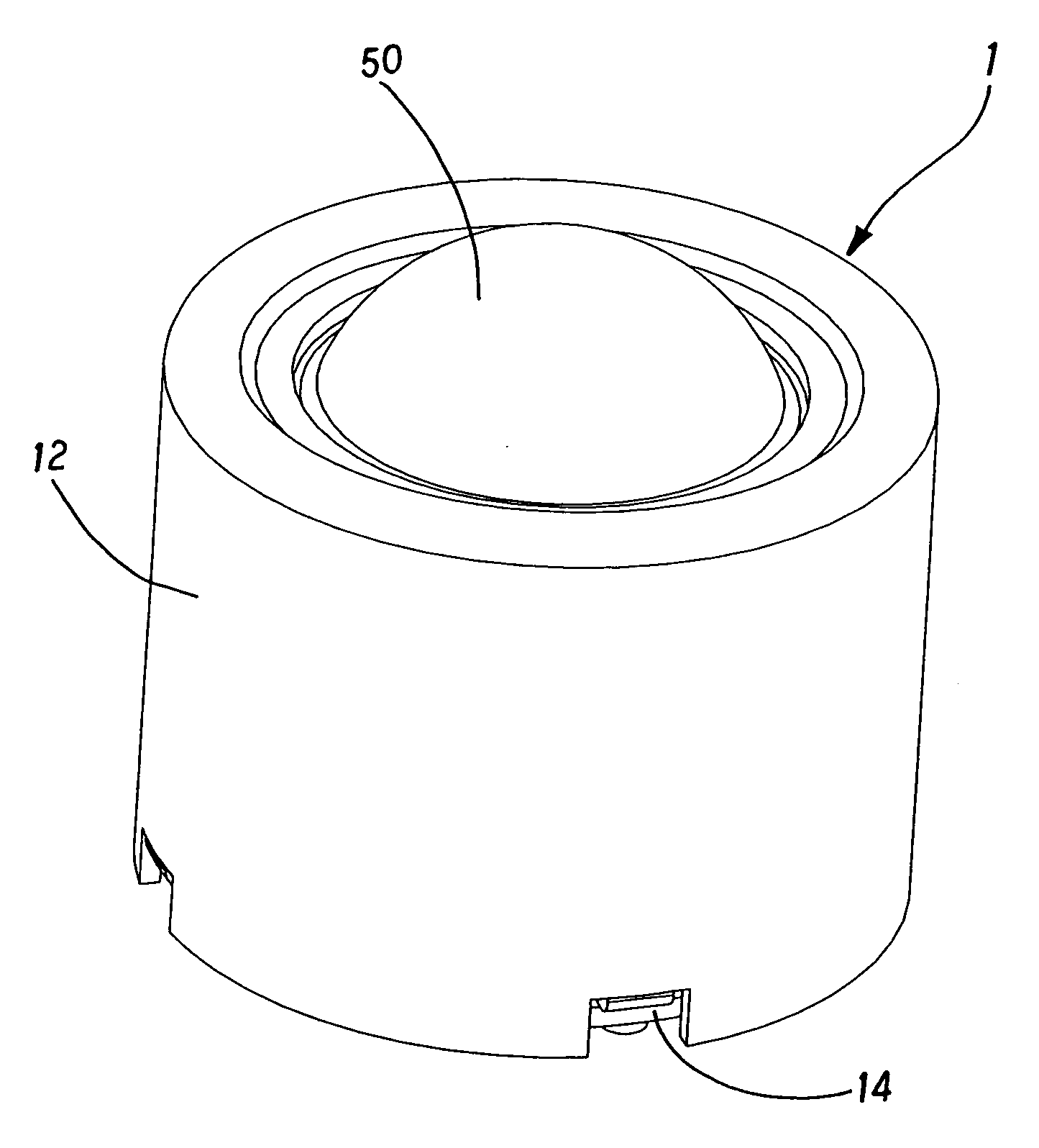
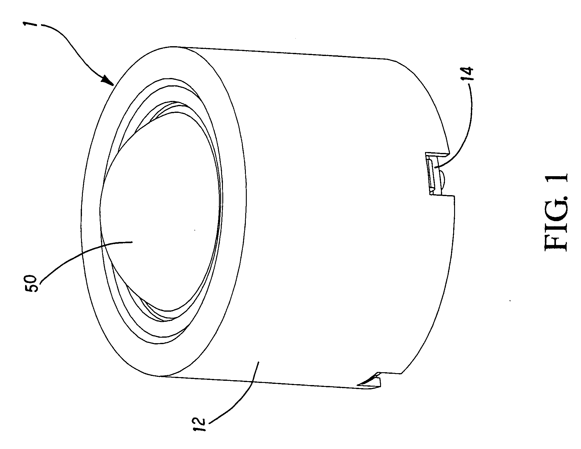
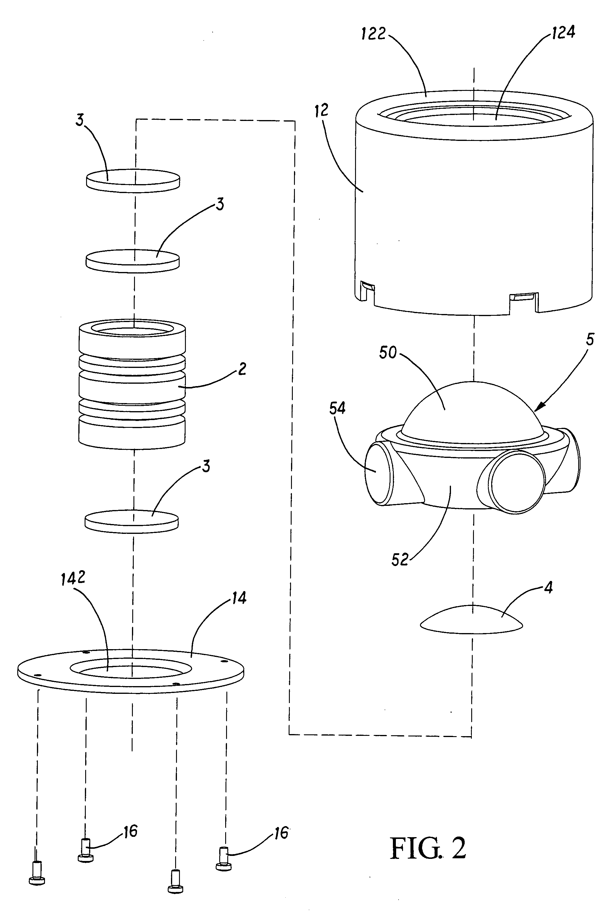
[0015]Referring to FIGS. 1 to 3 the structure of the present invention is illustrated. The magnetically-levitated telescopic land indicator 1 of the present invention has the following elements.

[0016]A sleeve 12 has an end surface 122. The end surface 122 has an opening 124.

[0017]A seat 14 has a downward concave portion 142. The seat 14 is combined to the sleeve 12 so as to form an inner space for receiving other elements. The seat 14 is combined to the sleeve 12 by studs 16. However other ways for combining the sleeve 12 to the seat 14 are permiss...


PUM


Abstract

A magnetically-levitated telescopic land indicator comprises a sleeve having an end surface; the end surface having an opening; a seat combined to the sleeve so as to form an inner space for receiving other elements; a magnetic levitated telescopic cylinder installed to the downward concave portion of the seat; the magnetically-levitated telescopic cylinder being installed in an inner space between the seat and the sleeve; at least two permanent magnets being installed within the magnetically-levitated telescopic cylinder; the permanent magnets having same magnetic polarities so that the permanent magnets being repulsive to one another; and an actuator being made of strengthened transparent material; the actuator having a dome shape protrusion at an upper end; an edge portion being arranged around an edge of the protrusion, and the protrusion protruding from the opening in the end surface of the sleeve.

Description

FIELD OF THE INVENTION[0001]The present invention relates to land indicators, and particularly to a magnetically-levitated telescopic land indicator, wherein permanent magnets are used to telescopically control a magnetically-levitated telescopic cylinder so as to avoid the elastic fatigue of the spring which is used in the prior art. Thus, the lifetime of the land indicator is prolonged. Furthermore, the permanent magnets can absorb a reflecting unit so as to prevent the reflecting unit from falling out.BACKGROUND OF THE INVENTION[0002]The land indicator in load has the effect of traffic safety. In daytime, if the car is shifted from the load, the car will compress the land indicator so as to alert the driver. At night, the land indicator can reflect light incident thereupon so as to project to the driver's eyes to alert the drivers.[0003]Initially, the land indicator is fixed to the ground and has a glass surface for reflecting light so as to reduce the friction force between the ...

Claims


Application Information

Patent Timeline
Patent Type & Authority Applications(United States)
IPC IPC(8): H02K7/09G02B7/182E01F9/50E01F9/506E01F9/524F21S2/00F21V17/00F21Y101/00
CPCH02N15/00
Inventor CHIANG, TSAI-JUNG
Owner CHIANG TSAI JUNG
Learn More