
Storage system

Active Publication Date: 2007-10-04
HITACHI LTD
View PDF6 Cites 38 Cited by
  • Summary
  • Abstract
  • Description
  • Claims
  • Application Information

AI Technical Summary

Benefits of technology

[0009] It is therefore an object of the present invention to provide a storage system capable of appropriately executing relocation or replication of a volume even in cases where there is no space in the storage tier specified as the transfer destination or replication destination for the empty volume.
[0031] According to the present invention, volume relocation or replication can be appropriately executed even when an empty volume does not exist in a storage tier designated as a transfer destination or replication destination of a volume. Further, according to the present invention, volume relocation or replication can be appropriately executed even when a volume designated as a transfer destination or replication destination of a volume is not an empty volume.

Problems solved by technology

When a plurality of storage apparatus are added to a storage system in accompaniment with an increase in the amount of data to be managed, configuration of the storage system becomes complex.
However, with the technology disclosed in Japanese Patent Laid-open Publication No. 2001-67187, it is necessary to relocate data every volume, and the operation is therefore complex.

Method used


Image

  • Storage system
  • Storage system
  • Storage system

Examples


embodiments

[0070] The following is a description with reference to each of the drawings of the embodiments of the present invention. Each embodiment by no means limits the scope of the patent claims and all of the features described in the embodiments are not limited to being mandatory as resolving means of the invention.

first embodiment

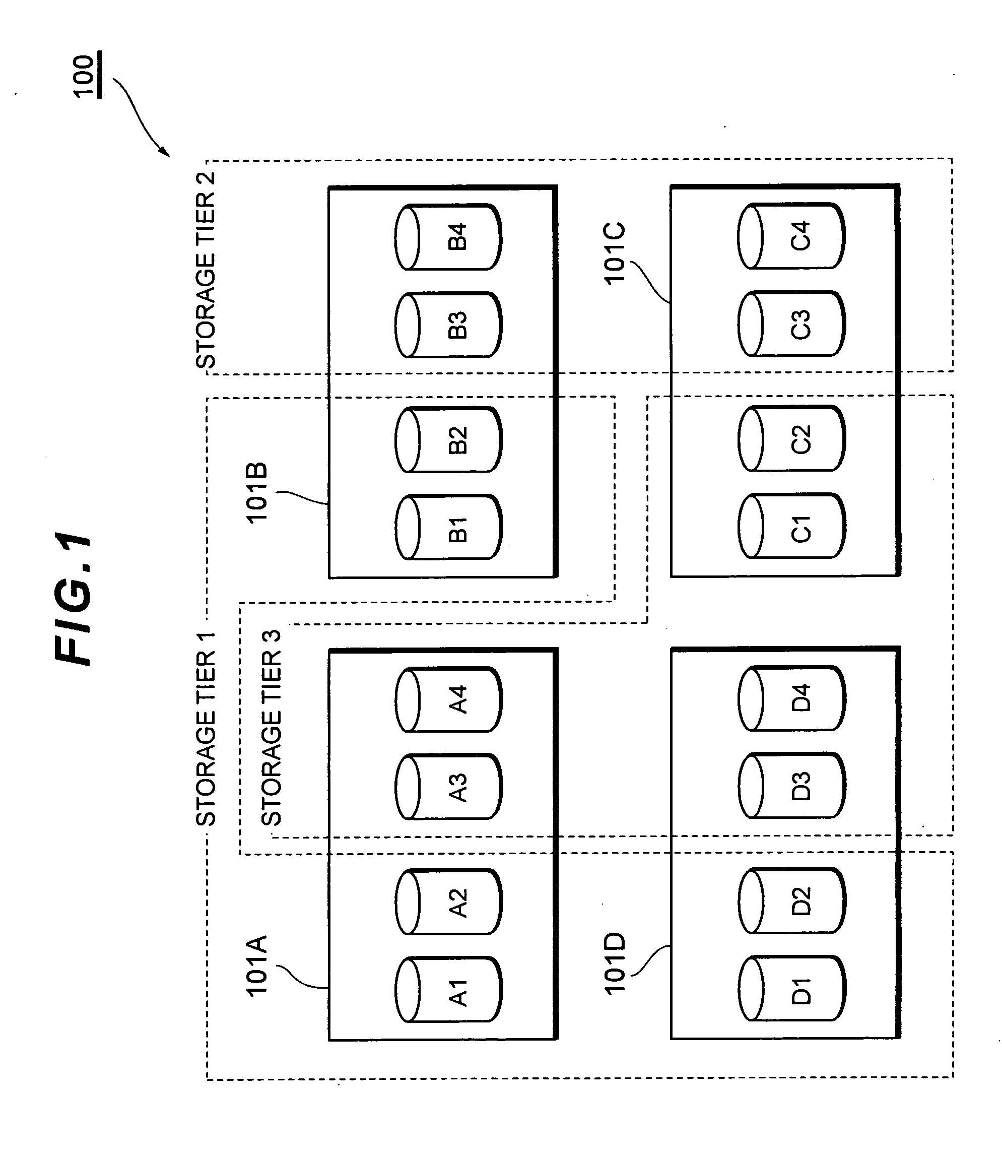
[0071] First, the overall concept of the embodiments is outlined with reference to FIG. 1 to FIG. 5. FIG. 1 shows a storage tier of a storage system 100 of the embodiments. The storage system 100 is equipped with a plurality of storage apparatus 101A, 101B, 101C and 101D. Volumes possessed by each storage apparatus 101A, 101B, 101C and 101D are collectively managed as a single logical storage resource. As a result, a host computer (refer to FIG. 10) recognizes the plurality of storage apparatus 101A, 101B, 101C and 101D as a single storage system 100.

[0072] Each storage apparatus 101A, 101B, 101C and 101D has respective volumes A1 to A4, B1 to B4, C1 to C4, and D1 to D4. These volumes are logical storage regions (logical volumes) defined on physical storage regions of storage devices (for example, hard disc drives, semiconductor memory drives, optical disc drives, magnetic tape media, etc.)

[0073] Each storage apparatus 101A, 101B, 101C and 101D may respectively be mounted with the...

second embodiment

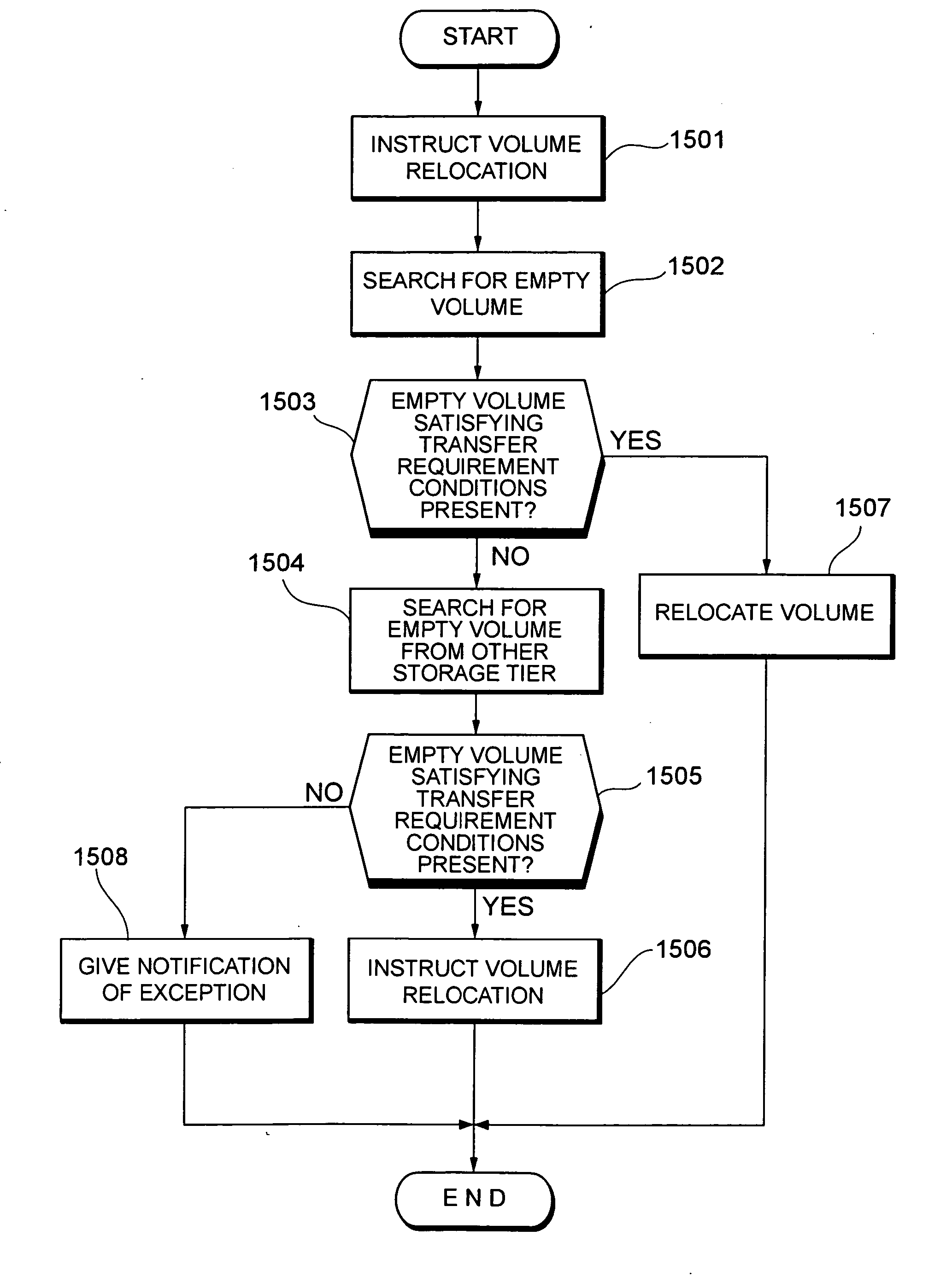
[0225] Next, a description is given of processing for relocating a certain volume to another volume, and processing for replication of a certain volume to this other volume. In the first embodiment described above, storage tiers are designated as a relocation destination or replication destination for a volume, but in the second embodiment, a volume is designated as a relocation destination or replication destination for a volume.

[0226] First, a description is given with reference to FIG. 31 and FIG. 32 of processing for relocating volume A to volume B.

[0227] As shown in FIG. 31, when an instruction to relocate volume A to volume B is provided by a user, the storage management server 102 checks whether or not volume B is an empty volume satisfying the transfer requirement conditions. The transfer requirement conditions can be said to be essential conditions required of a volume for a transfer destination, for example, “a transfer destination volume is a volume having storage capac...


PUM


Abstract

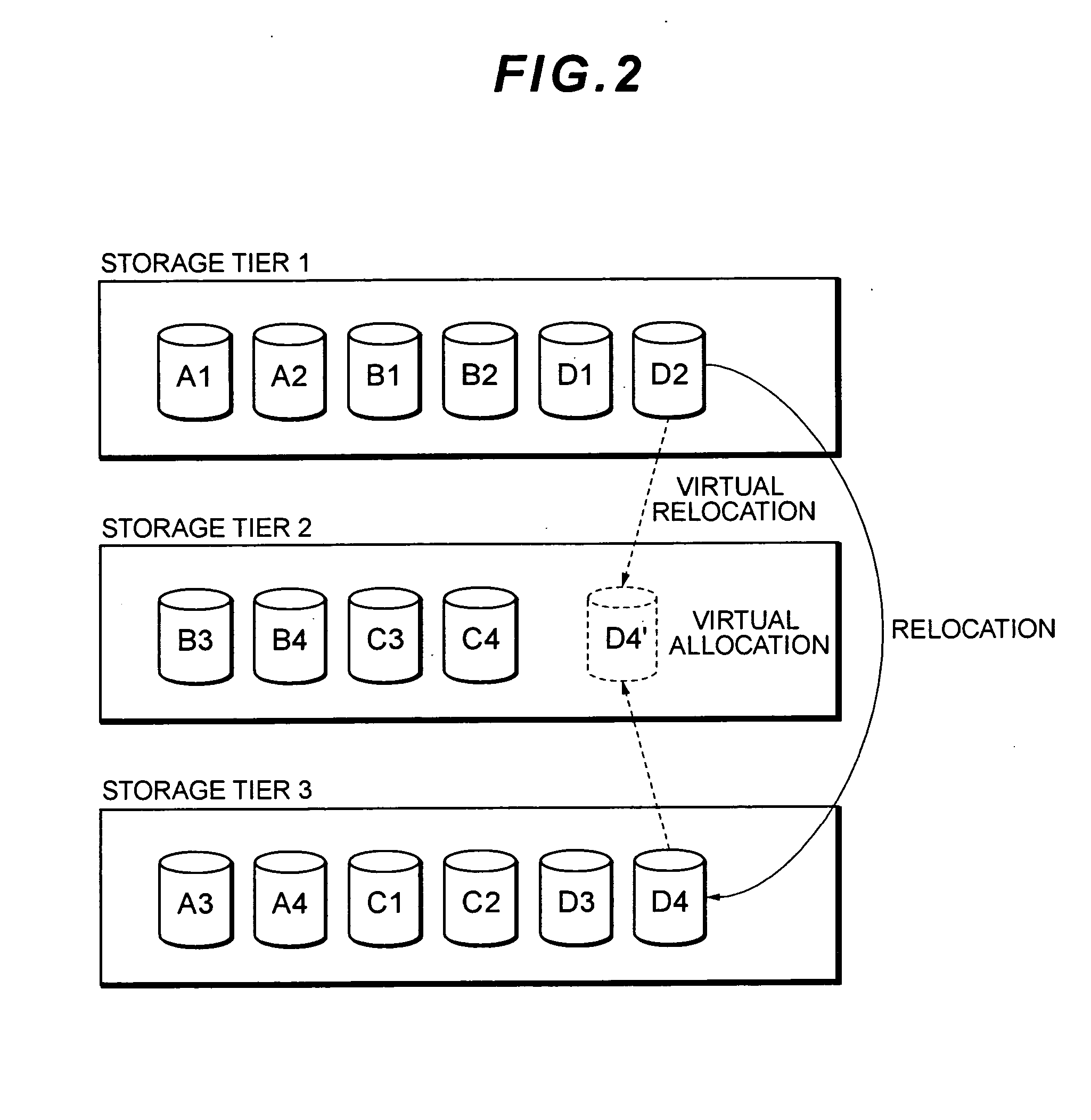
When a volume belonging to a first storage tier is relocated to a second storage tier, in the event that an empty volume satisfying capacity conditions is not present in the second storage tier, an empty volume satisfying the capacity conditions within volumes belonging to a third storage tier is virtually allocated to the second storage tier, a further virtual empty volume is formed, and the volume is virtually relocated to the further virtual empty volume.

Description

CROSS-REFERENCES TO RELATED APPLICATIONS [0001] This application relates to and claims priority from Japanese Patent Application No. 2006-102376, filed on Apr. 3, 2006, the entire disclosure of which is incorporated herein by reference. BACKGROUND [0002] 1. Field of the Invention [0003] The present invention relates to a storage system, and particularly relates to volume relocation technology and replication technology. [0004] 2. Description of Related Art [0005] Data handled by storage systems managed by business organizations, local authorities, public offices, financial institutions etc. increases year by year on the one hand, while new storage apparatus are added to or exchanged with existing storage apparatus in accompaniment with increase in the amount of data. When a plurality of storage apparatus are added to a storage system in accompaniment with an increase in the amount of data to be managed, configuration of the storage system becomes complex. Virtualization of a storage...

Claims


Application Information

Patent Timeline
IPC IPC(8): G06F13/00
CPCG06F3/0605G06F3/067G06F3/0649G06F3/061
Inventor MARUYAMA, TETSUYAEGUCHI, YOSHIAKIYAMAMOTO, MASAYUKI
Owner HITACHI LTD
Learn More