
Defining virtual shapes to position text and graphics

a technology of text and graphics, applied in the field of defining virtual shapes to position text and graphics, can solve the problems of not well adapted to the defining of table and pitch approach, affecting the shape of graphics on the sheet, and the desired shape is much more complex than a simple square or circl

Inactive Publication Date: 2007-10-04
CCL LABEL INC
View PDF33 Cites 12 Cited by
  • Summary
  • Abstract
  • Description
  • Claims
  • Application Information

AI Technical Summary

Benefits of technology

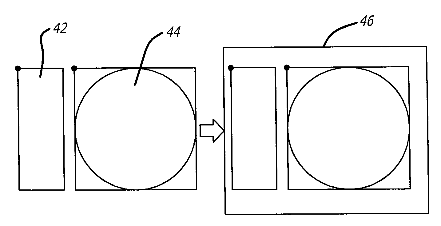
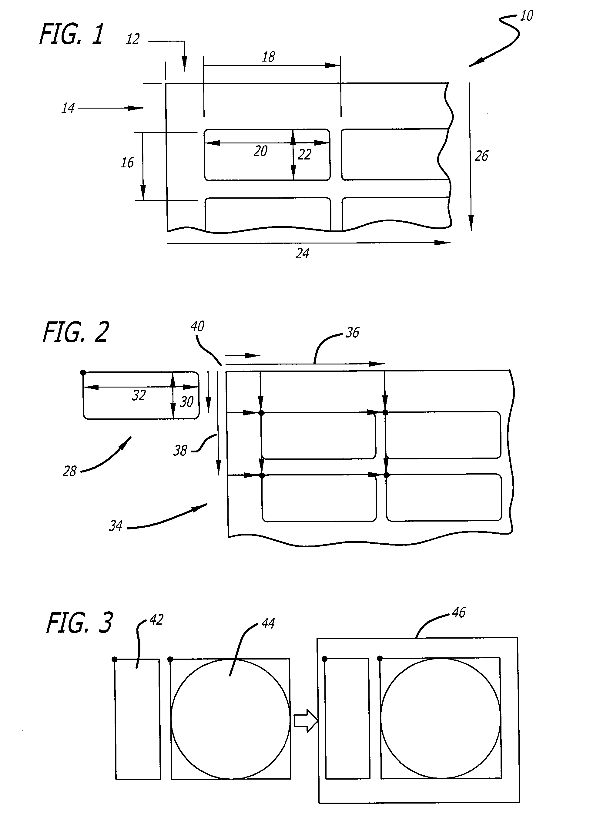
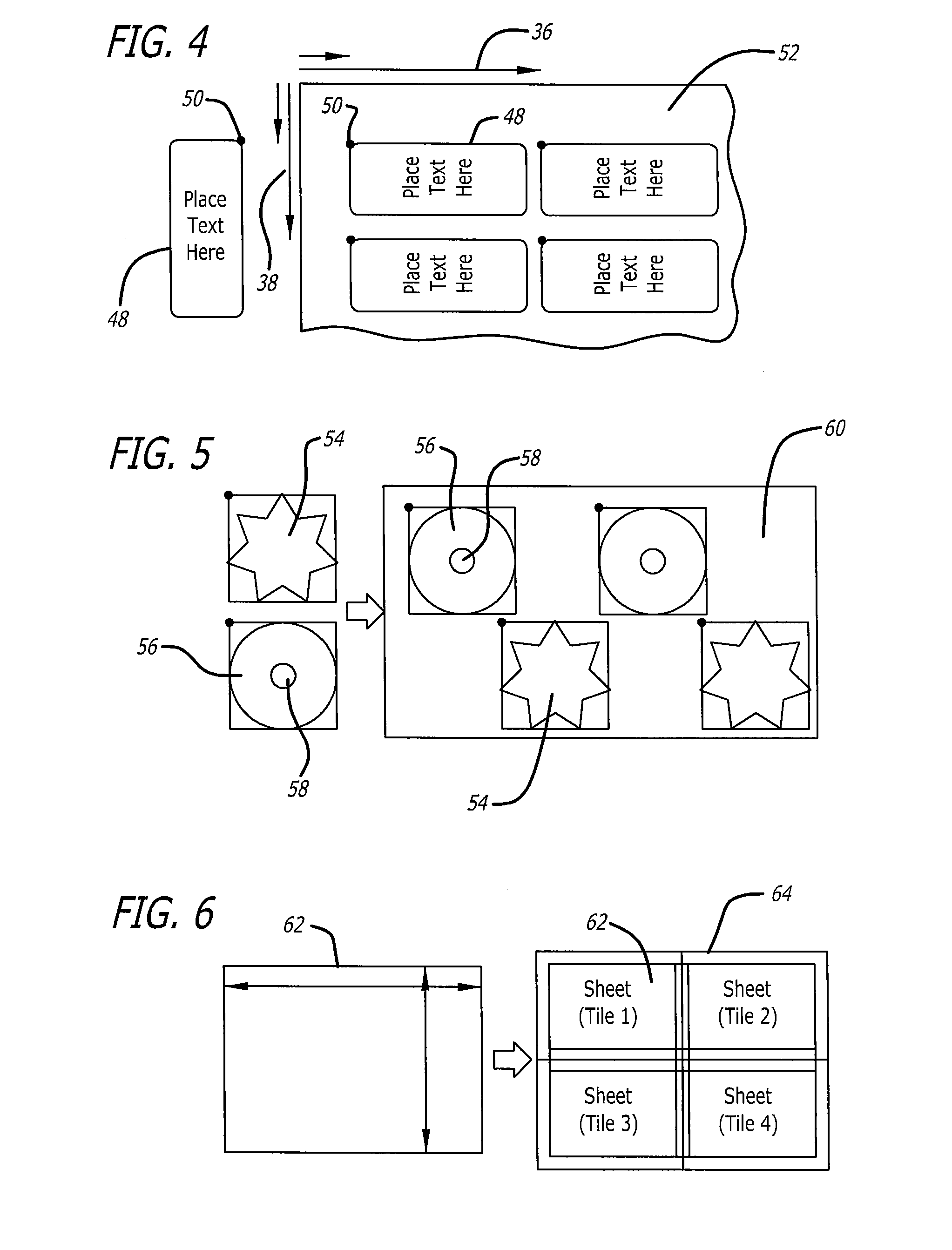
[0008]The present invention provides an application-independent collection of page demarcation instructions that is more robust than the table and pitch method described above. Unlike the table and pitch method, these new instructions define virtual shapes that are independent of the sheet. These virtual shapes, which can also be called “panels,” can then be referenced to one or more actual sheets using x-axis (left-to-right) and y-axis (top-down) coordinates, with respect to the top-left corner of the sheet, as well as respective rotations. The virtual shapes are typically not actually printed on the sheet, but are a concept used in positioning other information such as text and / or graphics and / or other information to be printed onto a sheet in the proper position on a particular sheet product.

Problems solved by technology

A drawback with this approach, however, relates to placing graphics on the sheet.
The table and pitch approach is not well adapted for defining where graphics are to be placed, and how they are to be placed on the sheet.
Often, the desired shape is much more complex than a simple square or circle.
When the item to be designed is a complex shape other than a simple circle or rectangle, for example, the table and pitch method can be cumbersome and inadequate to define predefined areas.
The table and pitch method is also not well suited for applications in which there are different shapes to be printed on one sheet, such as a label sheet on which there are different-shaped labels.
Another problem relates to “creep” and “crawl” errors, in which inaccuracies introduced using the table and pitch method are multiplied when the error occurs several times on a page.
A separate challenge has been how to accommodate new formats with existing software.
But then when a new type of card is developed, having a different layout, the existing software cannot accommodate the new card.

Method used


Image

  • Defining virtual shapes to position text and graphics
  • Defining virtual shapes to position text and graphics
  • Defining virtual shapes to position text and graphics

Examples


Embodiment Construction

[0032]As discussed above, the present invention relates to an application-independent collection of page demarcation instructions that is more robust than the table and pitch method described above. Unlike the table and pitch method, these new instructions define virtual shapes that are independent of the sheet. These virtual shapes, which can also be called “panels,” can then be referenced to one or more actual sheets using x-axis (left-to-right) and y-axis (top-down) coordinates, with respect to the top-left corner of the sheet.

[0033]In one embodiment of the present invention, an end-user can view a shape on a display, such as a computer monitor, a kiosk screen, the screen of a personal data assistant or other digital device. The shape may correspond, for example, to a complex label shape. After the user has customized and / or personalized text, graphics or other information to be printed, the software may apply a rotation to the shape as it is referenced onto the page to be printe...


PUM


Abstract

Virtual shapes are defined that are referenced to one or more actual, printable sheets for printing. The virtual shapes are referenced to the actual sheet using a rotation and x-axis (left-to-right) and y-axis (top-down) coordinates. The coordinates are typically specified with respect to the top-left corner of the sheet. In one example, an end-user views a shape on a display, such as a computer monitor, a kiosk screen, the screen of a personal data assistant or other digital device. The shape may correspond, for example, to a complex label shape. After the user has input customized and / or personalized text, graphics or other information to be printed, the software may apply a rotation to the virtual shape as it is referenced onto the actual page to be printed. A product identification table may be provided in order to correlate proper rotations and / or coordinates to particular types of commercial sheets. A single virtual shape may be referenced multiple times onto a single sheet. The virtual shape may be complex, such as a complex polygon and / or ellipse, and may include such features as cut-outs, blank areas to be kept free of text and / or graphics, multiple areas for printing text and / or graphics, as well as other complex features.

Description

CROSS-REFERENCE TO RELATED APPLICATION[0001]This is a non-provisional utility patent application based on Provisional Application Ser. No. 60 / 787,083, filed Mar. 29, 2006 and titled, “DEFINING VIRTUAL SHAPES TO POSITION TEXT AND GRAPHICS,” from which priority is hereby claimed and which is hereby incorporated by reference.BACKGROUND OF THE INVENTION[0002]For many years, a popular approach to defining a sheet for printing labels, tabs, cards and other related printable media, has used tables (columns and rows) in combination with pitch (a step-and-repeat process across and down the table). The table and pitch method is shown graphically in FIG. 1. A sheet 10 is represented in such terms as a side margin 12, top margin 14, vertical pitch 16, horizontal pitch 18, label width 20, label height 22, number across 24 and number down 26.[0003]A printable media, for example, was a metrical sheet that could be defined in terms of columns and rows. In simple applications, the goal was to simply...

Claims


Application Information

Patent Timeline
Patent Type & Authority Applications(United States)
IPC IPC(8): G06F17/00G06T1/00G06T11/20
CPCG06T11/60
Inventor LLOYD, DONALD S.NELSON, BRADLEY K.MCGEE, PHILLIP W.BAILEY, WYNNLEE, ROBERT P.ALBRECHT, KLAUS
Owner CCL LABEL INC
Learn More