Force monitoring system

Inactive Publication Date: 2007-10-11
ORTHO SENSING TECH
View PDF32 Cites 139 Cited by
  • Summary
  • Abstract
  • Description
  • Claims
  • Application Information

AI Technical Summary

Problems solved by technology

Some medical conditions may result in the degeneration of a human joint, causing a patient to consider and ultimately undergo joint replacement surgery.
The long-term success of the surgery oftentimes relies upon the skill of the surgeon and may involve a long, difficult recovery process.
As with all major surgical procedures, complications may occur.
While temporary components such as spacers and trials serve important purposes in gathering information prior to implantation of a permanent component, one drawback associated with temporary components is that a physician may need to “try out” different spacer or trial sizes and confi

Method used


Image

  • Force monitoring system
  • Force monitoring system
  • Force monitoring system

Examples


Embodiment Construction

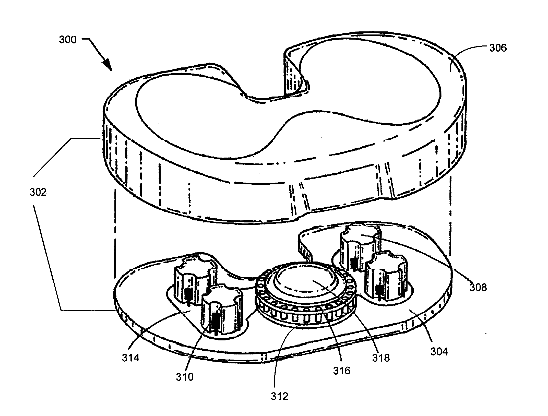
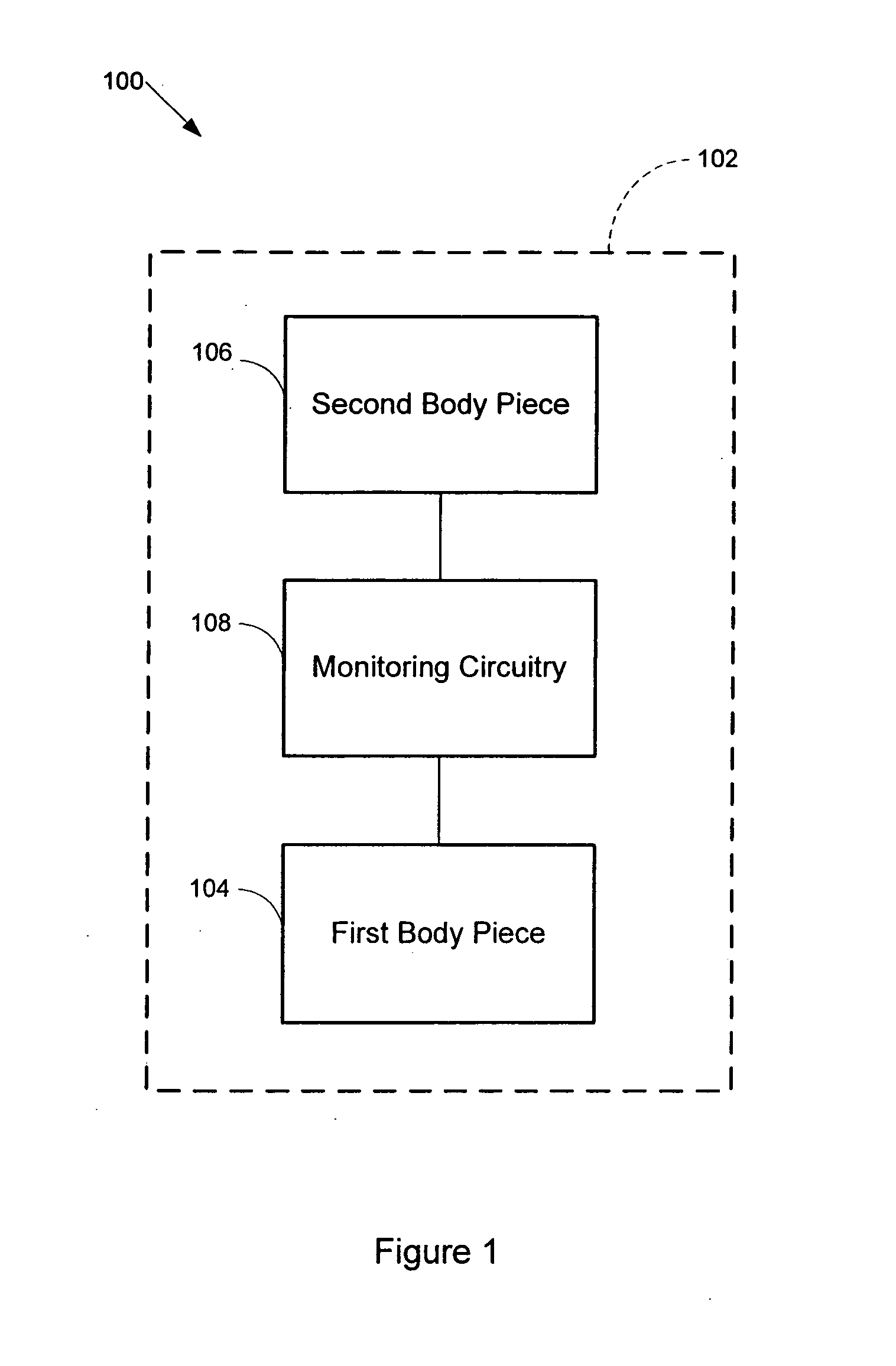
[0049]FIG. 1 is a diagram of a system 100 that monitors one or more forces between bearing surfaces, such as one or more dynamic contact forces, such as the force at contact between two bearing surfaces, or a dynamic contact force related measurement such as a strain, stress, torsion, and / or pressure. An enclosure 102 may comprise first body piece 104 (e.g., lower block) and second body piece 106 (e.g., upper block), each body piece comprising an inner surface and an outer surface. The first body piece and second body piece 104 and 106 are configured to mate together. The inner surface of first body piece 104 may comprise one or more protrusions, such as poles, posts, or beams, which are preferably integrally formed and which extend from a bearing surface. A portion of the inner surface of first body piece 104 may be recessed to receive some or all of monitoring circuitry 108. Alternatively, first body piece 104 may not include a recessed portion and monitoring circuitry 108 may ove...


PUM


Abstract

A system monitors dynamic forces between bearing surfaces. Based on sensed data, the system may model the forces on the bearing surfaces, analyze these forces, store data relating to these forces, and/or transmit data to an external data gathering device. The system includes a first body piece and a second body piece which mate together. The first and second body pieces comprise bearing surfaces that contact a material that may exert a force. A protrusion, such as a pole, post, or beam, extends from first body piece's bearing surface. At least one sensor is disposed on a pole. The at least one sensor detects a mechanical motion of the pole resulting from a force imposed on the body pieces, and generates data indicative of this force. A computer communicates with the at least one sensor and processes the sensed and/or modeled data.

Description

RELATED APPLICATIONS [0001] This application incorporates by reference applicant's co-pending applications U.S. patent application Ser. No. ______ (Attorney Docket No. 12462 / 4), filed concurrently herewith and entitled “Application of Neural Networks to Prosthesis Fitting and Balancing in Joints,” and U.S. patent application Ser. No. ______ (Attorney Docket No. 12462 / 5), filed concurrently herewith and entitled “Device and Method of Spacer and Trial Design During Joint Arthroplasty.”BACKGROUND [0002] 1. Technical Field [0003] The present disclosure relates to a monitoring system, and more particularly to a system that monitors forces between bearing surfaces. [0004] 2. Related Art [0005] Some medical conditions may result in the degeneration of a human joint, causing a patient to consider and ultimately undergo joint replacement surgery. The long-term success of the surgery oftentimes relies upon the skill of the surgeon and may involve a long, difficult recovery process. [0006] The...

Claims


Application Information

Patent Timeline
IPC IPC(8): G01B7/16
CPCA61F2/389A61F2/4657A61F2/4684G01L5/0019A61F2002/4666G01L1/2225A61F2002/30668
Inventor AMIROUCHE, FARIDLOPEZ ESPINA, CARLOS G.
Owner ORTHO SENSING TECH
Why Eureka
Try Eureka